Crankcase
| PART NUMBER | TOOL NAME |
| B-45520 | GEAR DETENT ASSEMBLY AID |
| B-45655 | CRANKCASE BEARING REMOVER/INSTALLER |
| B-45676-A | SPROCKET SHAFT SEAL/SPACER INSTALLER |
| HD-42326-B | CRANKSHAFT GUIDE TOOL |
| HD-42579-6 | SPROCKET SHAFT ADAPTER |
| HD-42579-A | SPROCKET SHAFT BEARING/SEAL INSTALLATION TOOL |
| HD-42720-2 | CRANKCASE BEARING REMOVER/INSTALLER BASE |
| J-5586-A | TRANSMISSION SHAFT RETAINING RING PLIERS |
| FASTENER | TORQUE VALUE | |
| Piston oil jet screw | 38-48 in·lbs | 4.3-5.4 Nm |
| Oil deflector plate screw: XR 1200X | 38-48 in·lbs | 4.3-5.4 Nm |
| Crankcase fastener | 15-19 ft·lbs | 20.3-25.8 Nm |
| Cylinder stud | 120-240 in·lbs | 13.6-27.1 Nm |
Installing piston oil jets
Notes:
- Damaged gaskets will result in either oil leakage or low oil pressure.
- See Figure 3-144. Gasket (4) is part of piston oil jet (2) assembly and is not sold separately.
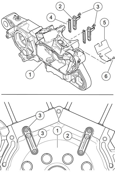
Figure 3-144. Piston oil jet assemblies: 1. Right crankcase; 2. Piston oil jet (2); 3. Screw (4); 4. Gasket (2); 5. Oil deflector plate (XR 1200X); 6. Screw (3) (XR 1200X)
1. See Figure 3-144. With oil jet pointed upward, install new piston oil jet assemblies (2) with gaskets (4) in right crankcase.
2. Apply LOCTITE 222 LOW STRENGTH THREADLOCKER AND SEALANT (purple) to TORX screws (3) and screws (6).
3. Install TORX screws to secure piston oil jet assembly to crankcase. Tighten to 38-48 in·lbs (4.3-5.4 Nm).
4. XR 1200X: Install oil deflector plate (5) using three screws (6). Tighten to 38-48 in·lbs (4.3-5.4 Nm).
Installing pinion shaft bearings
1. See Figure 3-145. Lubricate pinion shaft and pinion shaft bearing (2) with SCREAMIN' EAGLE ASSEMBLY LUBE.

Figure 3-145. Pinion shaft and left main bearings: 1. Outer bearing race; 2. Pinion shaft bearing; 3. Retaining ring; 4. Left main bearing; 5. Retaining ring; 6. Thrust washer; 7. Left main oil seal; 8. Retaining ring; 9. Sprocket shaft spacer
2. Slip bearing on pinion shaft.
3. See Figure 3-146. Using TRANSMISSION SHAFT RETAINING RING PLIERS (Part No. J-5586-A), install new retaining ring in groove of pinion shaft bearing inner race. Make sure retaining ring is fully seated in groove.

Figure 3-146. Installing pinion shaft bearing and retaining ring
Installing left main bearing
Note. When installing the left main bearing, the bearing presses from the inside of the left crankcase toward the outside. A shoulder is incorporated into the left crankcase which allows the bearing to be installed in one direction only.
1. See Figure 3-147. Using CRANKCASE BEARING REMOVER/INSTALLER (Part No. B-45655) and CRANKCASE BEARING REMOVER/INSTALLER BASE (Part No. HD-42720-2), press left main bearing into the left crankcase.

Figure 3-147. Installing left main bearing in crankcase: 1. Support tube (HD-42720-2); 2. Left crankcase; 3. Crankshaft bearing bore; 4. Left main bearing; 5. Pilot/driver (B-45655); 6. Press ram
a. Place support tube (1) on press bed with recessed cup end facing up.
b. With the inboard side of the left crankcase (2) facing upward, position crankshaft bearing bore (3) over support tube.
c. Place left main bearing (4) over bearing bore. Insert pilot/driver (5) through left main bearing, through crankshaft bearing bore and into support tube.
d. Apply pressure with press ram (6) until left main bearing bottoms out in bearing bore.
2. See Figure 3-148. Install new retaining ring from the inside of the left crankcase.

Figure 3-148. Installing left main bearing retaining ring
Assembling crankcase halves
1. Install transmission assembly in left crankcase. See 5.14 TRANSMISSION INSTALLATION.
Note. See Figure 3-149. The gear detent assembly Aid is used to move the gear detent lever clear of the shifter drum for assembly.
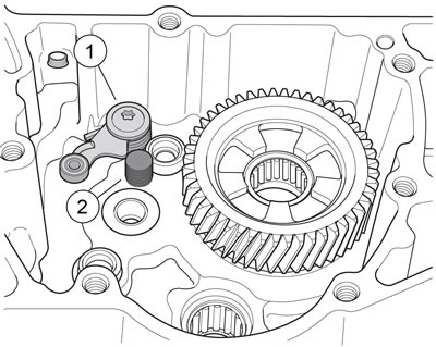
Figure 3-149. Using gear detent assembly aid (part No. B-45520): 1. Detent assembly; 2. Detent assembly aid
2. Retract detent assembly in right case half and install GEAR DETENT ASSEMBLY AID (Part No. B-45520) until it bottoms in right case half.
3. Shift transmission to 1st gear.
4. Lubricate left main bearing with SCREAMIN' EAGLE ASSEMBLY LUBE.
5. Assemble crankcase halves together.
- a. See Figure 3-150. Install flywheel assembly in right crankcase. Slide pinion shaft through outer race in right crankcase.
- b. Slide CRANKSHAFT GUIDE TOOL (Part No. HD-42326-B) onto flywheel sprocket shaft.
- c. Apply a thin coat of HARLEY-DAVIDSON HIGH-PERFORMANCE SEALANT - GRAY to crankcase joint faces.
- d. See Figure 3-151. Carefully fit crankcases together.
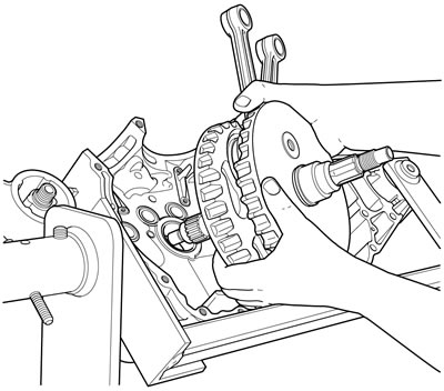
Figure 3-150. Installing flywheels in right crankcase
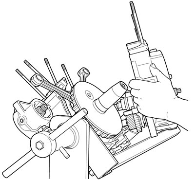
Figure 3-151. Assembling crankcases with crankshaft guide tool (part No. HD-42326-B)
Note. XR 1200X: See Figure 3-152. Install the double-ended bolt in position 8 to secure the front cylinder head oil return line.
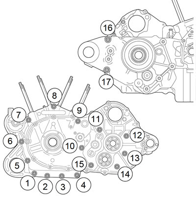
Figure 3-152. Crankcase fastener torque sequence
e. Apply a drop of LOCTITE 262 HIGH STRENGTH THREADLOCKER AND SEALANT (red) to last few threads of each crankcase fastener and install fasteners (thirteen long and four short) in crankcase assembly.
f. In sequence, tighten fasteners to 15-19 ft·lbs (20.325.8 Nm).
6. Remove transmission gear detent assembly aid.
7. See Figure 3-153 and Figure 3-154. Install spacer in ID of new seal. With the open (lipped) side of seal facing outward, center seal/spacer assembly over bearing bore.

Figure 3-153. Open side of seal faces out

Figure 3-154. Install spacer and seal
Notes:
- Removing spacer after installation requires seal procedure to be repeated.
- The XR 1200X requires the use of the SPROCKET SHAFT ADAPTER (Part No. HD-42579-6).
8. See Figure 3-155. Install bearing seal and spacer.
- a. Center seal/spacer driver (2) over seal, so that the sleeve (smaller O.D.) seats between seal wall and garter spring.
- b. Assemble SPROCKET SHAFT BEARING/SEAL INSTALLATION TOOL (Part No. HD-42579-A) (1) and SPROCKET SHAFT SEAL/SPACER INSTALLER (Part No. B-45676-A) onto sprocket shaft.
- c. Rotate handle clockwise until the spacer makes contact with the bearing. Remove tool from sprocket shaft.
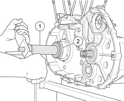
Figure 3-155. Install bearing seal/spacer: 1. Bearing/seal installer (Part No. HD-42579-A); 2. Seal/spacer installer (Part No. B-45676-A)
9. Install retaining ring into groove in sprocket shaft bearing bore.
Installing cylinder base studs
See Figure 3-156. If cylinder studs were removed, install them as follows:
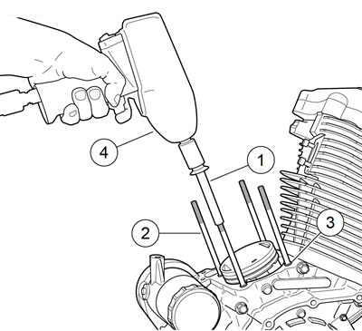
Figure 3-156. Cylinder studs: 1. Head screw with ball inside; 2. Cylinder stud; 3. Shoulder on cylinder stud; 4. Air gun
1. Pack clean towels into crankcase opening.
2. Place a steel ball into a head screw (1).
3. The cylinder studs (2) have a shoulder (3) at the lower end. Place the end of the studs without the shoulder into the head screw.
4. Install the studs in the crankcase with the shoulder end down. Use an air gun (4) to drive the stud until the shoulder reaches the crankcase.
5. Remove air gun. Use a torque wrench to tighten studs to 120-240 in·lbs (13.6-27.1 Nm).
Cam and pinion gear identification
Note. Prior to changing any cam gears, check gear shaft fit within corresponding bushings. Worn bushings can cause excessive backlash.
See Figure 3-157. Cam lobes are stamped with a number (1, 2, 3, or 4) followed by a letter. The number identifies the cam location/function. The letter identifies the cam lobe profile. Refer to Table 3-42.
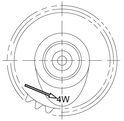
Figure 3-157. Cam identification (typical)
Table 3-42. Cam identification
| CAM LOCATION | XL | XR |
| Rear exhaust | 1W | 1S |
| Rear intake | 2W | 2S |
| Front intake | 3W | 3S |
| Front exhaust | 4W | 4S |
Cam gears and gearcase cover: xl models
| PART NUMBER | TOOL NAME |
| HD-43984 | CRANKSHAFT LOCKING TOOL |
| FASTENER | TORQUE VALUE | |
| Pinion shaft locking nut: XR 1200X | 19-21 ft·lbs | 26-29 Nm |
| Gearcase cover fastener | 90-120 in·lbs | 10.2-13.6 Nm |
1. See Figure 3-158. Make sure shaft key (1) is installed on flywheel pinion shaft. Install oil pump drive gear (10) and pinion gear (9) on pinion shaft.

Figure 3-158. Gearcase cover and cam gears: 1. Fastener; 2. Cover; 3. Gasket; 4. Rear exhaust cam; 5. Rear intake cam; 6. Front intake cam; 7. Front exhaust cam; 8. Nut; 9. Pinion gear; 10. Oil pump drive gear; 11. Shaft key
Note. See Figure 3-159. Timing mark on pinion gear tooth is aligned with keyway in ID of pinion gear. The timing mark will allow you to easily position pinion gear over shaft key and against oil pump drive gear on pinion shaft.

Figure 3-159. Pinion gear timing mark and keyway: 1. Keyway; 2. Timing mark at center line of keyway
2. See Figure 3-158. Clean threads on pinion shaft and nut (8). Apply several drops of LOCTITE 262 HIGH STRENGTH THREADLOCKER AND SEALANT (red) to threads of nut.
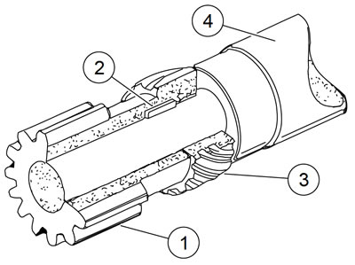
Figure 3-160. Oil pump drive gear and pinion gear installed on pinion shaft: 1. Pinion Gear; 2. Shaft key; 3. Oil pump drive gear; 4. Pinion shaft
Note. When using CRANKSHAFT LOCKING TOOL, do NOT use impact wrench to drive nut onto pinion shaft.
3. See Figure 3-161. Install pinion shaft nut.
- a. Install CRANKSHAFT LOCKING TOOL (Part No. HD-43984) over pinion shaft.
- b. Install nut on pinion shaft.
- c. Tighten to 19-21 ft·lbs (26-29 Nm).
- d. Tighten an additional 15-19 degrees of rotation.
- e. Remove CRANKSHAFT LOCKING TOOL (Part No. HD-43984).
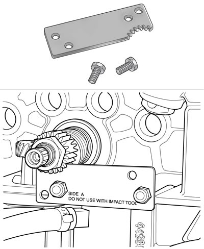
Figure 3-161. Crankshaft locking tool (part No. HD-43984)
Note. See Figure 3-162. Install rear exhaust and front intake cam gears before rear intake cam gear. This prevents an alignment problem with the pinion gear.

Figure 3-162. Cam, pinion gear and timing mark indexing (cam #2 "V" marks are not used for timing): 1. Rear exhaust cam gear (1W); 2. Rear intake cam gear (2W); 3. Front intake cam gear (3W); 4. Front exhaust cam gear (4W); 5. Pinion gear
4. Lubricate all cams and all cam bushings in right crankcase with SCREAMIN' EAGLE ASSEMBLY LUBE.
5. See Figure 3-162. Rotate crankshaft until timing mark on pinion gear points exactly at centerline of rear intake cam bushing.
6. See Figure 3-158. Install rear exhaust cam (4). Rotate cam until timing mark (a slot) points exactly at center line of rear intake cam bushing.
7. Install front intake cam (6). Rotate cam until slotted timing mark points exactly at center line of rear intake cam bushing.
Note. See Figure 3-162. "V" marks on rear intake cam are not used for timing of Sportster model engines.
8. See Figure 3-158. Install rear intake cam (5). As you install this cam, rotate it so that the three timing marks (dots) line up exactly with timing marks on the pinion gear, rear exhaust cam and front intake cam.
9. Install front exhaust cam (7). Rotate the cam to line up the timing mark with the timing mark of the front intake cam.
10. See Figure 3-162. Verify timing marks. If necessary, remove a cam, rotate it slightly, and install. If timing marks are off even one tooth, engine will not run correctly.
11. See Figure 3-158. Install a new dry gasket (3) on gearcase cover (2).
12. Lubricate all cam bushings in gearcase cover with SCREAMIN' EAGLE ASSEMBLY LUBE.
13. Install gearcase cover. Secure coverto crankcase with 11 fasteners.
14. See Figure 3-163. Tighten in sequence to 90-120 in·lbs (10.2-13.6 Nm).
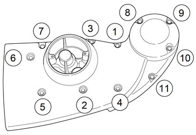
Figure 3-163. Gearcase cover mounting screw torque sequence
15. Gauge cam gear end play. See 3.17 BOTTOM END OVERHAUL: DISASSEMBLY, Cam Gear End Play.
Cam gears and gearcase cover: XR 1200X
| PART NUMBER | TOOL NAME |
| HD-43984 | CRANKSHAFT LOCKING TOOL |
| FASTENER | TORQUE VALUE | |
| Pinion shaft locking nut: XR 1200X | 19-21 ft·lbs | 26-29 Nm |
| Gearcase cover fastener | 90-120 in·lbs | 10.2-13.6 Nm |
| Oil pump rotor cover screw: XR 1200X | 90-120 in·lbs | 10.2-13.6 Nm |
| Checkvalve housing fastener: XR 1200X | 90-120 in·lbs | 10.3-13.6 Nm |
| Gearcase cover fastener | 90-120 in·lbs | 10.2-13.6 Nm |
1. See Figure 3-164. Make sure t-key (9) is installed on flywheel pinion shaft. Install spacer (6) and pinion gear (5) on pinion shaft.
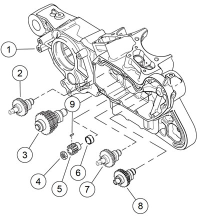
Figure 3-164. Gearcase and valve train components: XR 1200X: 1. Right crankcase half; 2. Rear exhaust cam gear; 3. Rear intake cam gear; 4. Nut; 5. Pinion gear; 6. Spacer; 7. Front intake cam gear; 8. Front exhaust cam gear; 9. T-key
Note. See Figure 3-165. Timing mark on pinion gear tooth is aligned with keyway in ID of pinion gear. The timing mark will allow you to easily position pinion gear over t-key and against oil pump drive gear on pinion shaft.
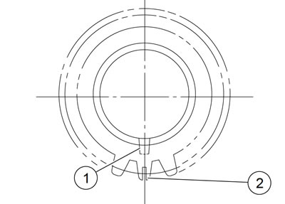
Figure 3-165. Pinion gear timing mark and keyway: 1. Keyway; 2. Timing mark at centerline of keyway
2. See Figure 3-164. Clean threads on pinion shaft and nut (4). Apply several drops of LOCTITE 262 HIGH STRENGTH THREADLOCKER AND SEALANT (red) to threads of nut.
Note. When using CRANKSHAFT LOCKING TOOL, do NOT use impact wrench to drive nut onto pinion shaft.
3. See Figure 3-166. Install CRANKSHAFT LOCKING TOOL (Part No. HD-43984) over pinion shaft. Install nut on pinion shaft. Tighten to 19-21 ft·lbs (26-29 Nm). Then tighten nut 15-19 degrees of rotation. Remove CRANKSHAFT LOCKING TOOL (Part No. HD-43984).
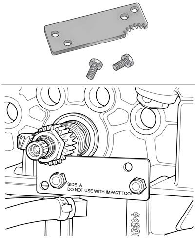
Figure 3-166. Crankshaft locking tool (part No. HD-43984)
Note. Because of the larger diameter gear on the outboard end of the rear intake cam gear, install the rear exhaust and front intake cam gears before the rear intake cam gear.
4. Lubricate all cams and all cam bores in right crankcase with SCREAMIN' EAGLE ASSEMBLY LUBE.
5. See Figure 3-167. Rotate crankshaft until timing mark on pinion gear points exactly at centerline of rear intake cam bore.
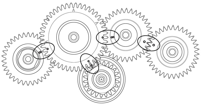
Figure 3-167. Cam and pinion gear timing marks: XR 1200X (V-marks are not used for timing)
6. Install rear exhaust cam. Rotate cam until timing mark (a slot) points exactly at centerline of rear intake cam bore.
7. Install front intake cam. Rotate cam until slotted timing mark points exactly at centerline of rear intake cam bore.
Note. V marks on rear intake cam are not used for timing of Sportster model engines.
8. Install rear intake cam. Rotate the cam to line up the three timing marks (dots) exactly with timing marks on the pinion gear, rear exhaust cam and front intake cam.
9. Install front exhaust cam. Rotate the cam to line up its timing mark (a dot) with timing mark (dot) of front intake cam.
10. Verify timing marks. If necessary, remove a cam, rotate it slightly and replace it. If timing marks are off even one tooth, engine will not run correctly.
11. Lubricate all cam bores in gearcase cover with engine oil.
12. See Figure 3-168. Install gearcase coverwith new gasket and secure with three fasteners (6). Tighten fasteners to 90-120 in·lbs (10.2-13.6 Nm).
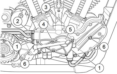
Figure 3-168. Gearcase cover and oil pump: XR 1200X: 1. Rigid lines; 2. Vent hose; 3. Check valve screws (2); 4. Oil pump cover screw (6); 5. Oil pump cover; 6. Gearcase cover fastener (3)
13. Install oil pump rotors. Orient the rotors as removed.
14. Install new O-rings in oil pump cover and install using six fasteners (4). Tighten to 90-120 in·lbs (10.2-13.6 Nm).
15. Install check valve housing using a new base O-ring. Tighten fasteners (3) to 90-120 in·lbs (10.3-13.6 Nm).
16. Connect rigid lines (1) and vent hose (2). See 3.12 PRECISION COOLING SYSTEM: XR 1200X, Oil Pump Lines.
17. See Figure 3-169. Install gearcase and oil pump cover. Secure with 9 socket fasteners. Tighten in the sequence shown to 90-120 in·lbs (10.2-13.6 Nm).
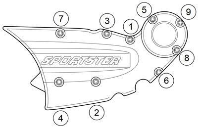
Figure 3-169. Oil pump cover torque sequence: XR 1200X
18. Gauge cam gear end play. See 3.17 BOTTOM END OVERHAUL: DISASSEMBLY, Cam Gear End Play.
Tappets
| FASTENER | TORQUE VALUE | |
| Tappet cover, anti-rotation mounting screw | 90-120 in·lbs | 10.2-13.6 Nm |
See Figure 3-170. The tappet and roller (4), under compression force from valve spring, follow the surface of the revolving cam. The up-and-down motion is transmitted to the valve by the pushrod and rocker arm. The tappet contains a piston (2) and cylinder. The check valve (3) allows the unit to fill with engine oil (1) reducing clearance in the valve train. The unit automatically compensates for heat expansion to maintain minimal clearances between the cam and the pushrod.
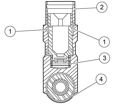
Figure 3-170. Tappet assembly: 1. Oil; 2. Piston; 3. Check valve; 4. Roller
It is normal for tappets to click when engine is started after standing for some time. Tappets have a definite leakdown rate which permits the oil in the tappets to escape. This allows units to compensate for various expansion conditions of parts and still maintain minimal clearances. Tappets are functioning properly if they become quiet after a few minutes of engine operation.
Cleaning and inspection
Warning! Compressed air can pierce the skin and flying debris from compressed air could cause serious eye injury. Wear safety glasses when working with compressed air. Never use your hand to check for air leaks or to determine air flow rates.
1. Clean all parts, except roller/tappet assembly, in solvent. Blow dry with compressed air.
2. Measure valve tappet OD and crankcase bore ID to calculate clearance. If guide clearance exceeds specification, replace the tappets and/or crankcases. Refer to Table 3-43.
3. Measure tappet roller free play. Recommended service practice is tappet replacement.
4. Measure tappet roller end clearance.
5. Soak tappets in clean engine oil and kept covered until assembly.
6. Apply SCREAMIN' EAGLE ASSEMBLY LUBE to rollers and OD of tappet before installation.
Table 3-43. Valve tappet specifications
| ITEM | SERVICE WEAR LIMIT | |
| in | mm | |
| Tappet clearance in guide | 0.0030 | 0.076 |
| Tappet roller free play (clearance on pin) | 0.0015 | 0.038 |
| Tappet roller end clearance | 0.026 | 0.660 |
Installation
1. See Figure 3-171. Rotate engine so that both tappets (3) from the cylinder being serviced will be installed on the base circle (lowest position) of the cam.
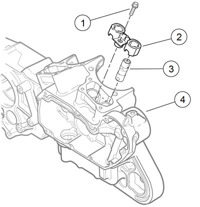
Figure 3-171. Tappet components: 1. Screw (2); 2. Anti-rotation device (2); 3. Tappet (4); 4. Right crankcase
2. Apply a liberal amount of engine oil to tappet assembly (especially roller needles) for smooth initial operation.
Note. Face the flats of the tappets front and rear when installed in the engine and with the oil feed hole toward the gear cover.
3. Insert the intake and exhaust tappets into the anti-rotation blocks (2).
4. Install anti-rotation blocks with tappets into bore in right crankcase (4). Secure with screw (1). Tighten to 90-120 in·lbs (10.2-13.6 Nm).
Note. The front tappet cover has a tab on the front or right side. The rear tappet cover has a tab on the rear or left side.
5. Install the tappet covers, pushrod covers, and pushrods. See 3.16 TOP END OVERHAUL: ASSEMBLY, Tappet Covers, Pushrod Covers and Pushrods.
