
Bushing inspection and removal: XL only
| PART NUMBER | TOOL NAME |
| HD-95760-69A | BUSHING AND BEARING PULLER |
Note. The camshaft and pinion gear shafts are supported by bushings in both the cover and the crankcase.
1. See Figure 3-114. Measure each bushing and its corresponding cam gear shaft or pinion gear shaft. Replace bushings that exceed service wear limits. Refer to Table 3-34.
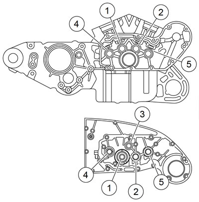
Figure 3-114. Cam and pinion bushings: 1. Rear intake; 2. Front intake; 3. Pinion; 4. Rear exhaust; 5. Front exhaust
2. See Figure 3-115. Use BUSHING AND BEARING PULLER (Part No. HD-95760-69A) to remove bushings from gearcase cover and crankcase.
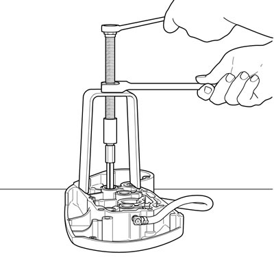
Figure 3-115. Removing cam bushing from gearcase cover
Table 3-34. Cam and pinion shaft specifications
| SHAFT | CORRECT CLEARANCE | SERVICE WEAR LIMIT | ||
| in | mm | in | mm | |
| Cam | 0.0007-0.0022 | 0.018-0.056 | 0.003 | 0.08 |
| Pinion | 0.0023-0.0043 | 0.058-0.109 | 0.005 | 0.13 |
Bushing installation: XL only
Note. Installing and reaming crankcase and gearcase cover bushings can alter the center distances between mating gears. Incorrect spacing can damage gears and increase gear noise.
Cam gear bushings in right crankcase
See Figure 3-116. Each cam gear bushing installed in right crankcase must be positioned with its oiling slot at exact top of bore (12 o'clock position).
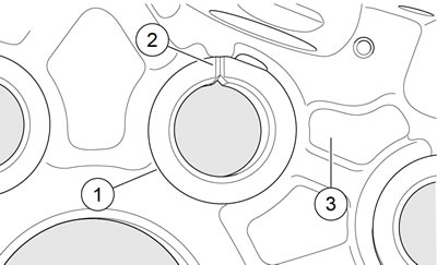
Figure 3-116. Cam gear bushing installed in crankcase: 1. Cam gear bushing; 2. Slot at top; 3. Right crankcase
1. Using an arbor press, install each bushing in crankcase bore until bushing shoulder contacts crankcase boss.
2. Ream the new bushing to size after installation. See 3.18 GEARCASE: XL MODELS, Bushing Reaming: XL Only.
Cam gear bushings (except rear intake bushing) in gearcase cover
1. Using an arbor press, install each bushing in its gearcase cover bore so that bushing shoulder contacts cover boss. There is no need to orient these particular bushings in any specific position of rotation within gearcase cover bores.
2. Line-ream the new bushing to correct size after installation. See 3.18 GEARCASE: XL MODELS, Bushing Reaming: XL Only.
Rear intake cam gear bushing in gearcase cover
Rear intake cam gear bushing must be installed in its gearcase cover bore using an arbor press. The bushing must be oriented in a specific position of rotation within the cover bore.
1. See Figure 3-117. Position bushing (1) over bore of gearcase cover (2) with chamfered edge downward and slot upward. Align slot in bushing with slot in gearcase cover boss. Press bushing into cover bore until bushing is flush with cover boss.
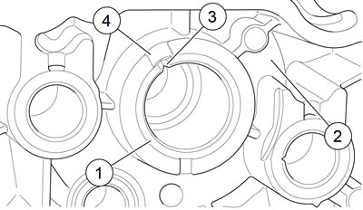
Figure 3-117. Rear intake cam gear bushing installed in gearcase cover: 1. Rear intake cam gear bushing; 2. Gearcase cover; 3. Cam bushing slot; 4. Gearcase cover slot
2. Line-ream the new bushing to correct size after installation. See 3.18 GEARCASE: XL MODELS, Bushing Reaming: XL Only.
Pinion shaft bushing in gearcase cover
1. Using an arbor press, install pinion shaft bushing in gearcase cover flush with cover boss. This bushing requires no specific orientation.
2. See Figure 3-118. The replacement bushing must be secured from rotation by installation of a dowel pin. Drill a No. 31 hole, 0.281 in (7.14 mm) deep, attop side of boss (side toward top of gearcase cover). Center drill bit so hole is drilled half in bushing and half in cover.
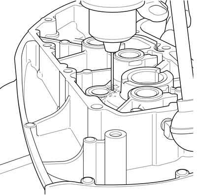
Figure 3-118. Drilling pinion bushing dowel pin hole in gearcase cover
3. Drive a new dowel pin no more than 0.020 in (0.51 mm) below the bushing face. Carefully peen edges of hole to lock the pin in place.
4. Line-ream the new bushing to correct size after installation. See 3.18 GEARCASE: XL MODELS, Bushing Reaming: XL Only.
Bushing reaming: XL only
| PART NUMBER | TOOL NAME |
| HD-38871 | CRANKSHAFT BUSHING PLATE PILOT |
| HD-94803-67 | REAR INTAKE CAM GEAR BUSHING REAMER |
| HD-94812-1 | REAMER |
| HD-94812-87 | PILOT |
Notes:
- Installing and reaming crankcase and gearcase cover bushings can alter the center distances between mating gears. Incorrect spacing can damage gears and increase gear noise.
- Bushings in right crankcase serve as pilots for reaming gearcase cover bushings and must, therefore, be reamed to size first.
- After reaming any bushing, check shaft fit in the bushing. It may be necessary to make a second pass with reamer to attain proper fit.
Cam gear bushings in right crankcase
1. Separate two halves of crankcase, if not already done. Place right crankcase on flat surface with gearcase side up.
2. See Figure 3-119. Position CRANKSHAFT BUSHING PLATE PILOT (Part No. HD-38871) onto gearcase side of crankcase. The upper right and lower left indexing holes in pilot must be placed over dowels in crankcase. Insert two bolts (supplied with pilot) through two remaining holes in pilot, and into threaded holes of crankcase. Tighten bolts securely.
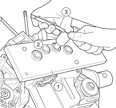
Figure 3-119. Reaming cam gear bushing in right crankcase: 1. Camshaft bushing reamer pilot (Part No. HD-38871); 2. Standard 11/16 reamer; 3. Reamer handle
3. Insert a standard 11/16 reamer through pilot hole and into bushing while turning reamer clockwise. Continue turning reamer clockwise through bushing until smooth shank of reamer passes through hole in pilot.
4. Detach reamer from handle. Pull reamer out opposite side of crankcase.
Warning! Compressed air can pierce the skin and flying debris from compressed air could cause serious eye injury. Wear safety glasses when working with compressed air. Never use your hand to check for air leaks or to determine air flow rates.
5. Thoroughly clean right crankcase, removing all metal chips/shavings. Blow out all bushing bores and oil passages using low pressure compressed air.
Cam gear bushings (except rear intake bushing) in gearcase cover
Note. Newly installed cam gear bushings must be line-reamed to establish correct clearance and to produce perfect alignment. Use the right crankcase as a pilot for the reamer. If crankcase halves are not separated, use a spare right crankcase to perform the following line-reaming procedures.
1. Bushings to be reamed must be installed in gearcase cover as described in 3.18 GEARCASE: XL MODELS, Bushing Installation: XL Only. Attach gearcase cover to right crankcase, which has been disassembled from left crankcase, securing with a minimum of three mounting screws.
2. Insert a standard 11/16 reamer through the previously reamed cam gear bushing in right crankcase, which is in line with one of the bushings to be reamed in gearcase cover.
3. Turn reamer clockwise through bushing in cover until reamer bottoms. Then give reamer one complete clockwise turn to size the bushing. Continue turning reamer clockwise while extracting reamer from bushing.
4. Repeat two previous steps for remaining two cam gear bushings (except rear intake bushing) in gearcase cover, if required.
5. Separate gearcase cover from right crankcase. Inspect bushings for proper cam gear shaft fit. Repeat line reaming operation if necessary.
Warning! Compressed air can pierce the skin and flying debris from compressed air could cause serious eye injury. Wear safety glasses when working with compressed air. Never use your hand to check for air leaks or to determine air flow rates.
6. Thoroughly clean gearcase cover, removing all metal chips/shavings. Blow out all bushing bores and oil passages using low pressure compressed air.
Rear intake cam gear bushing in gearcase cover
Note. Newly installed cam gear bushings must be line-reamed to establish correct clearance and to produce perfect alignment. Use the right crankcase as a pilot for the reamer. If crankcase halves are not separated, use a spare right crankcase to perform the following line reaming procedures.
1. Rear intake cam gear bushing must be installed in gearcase cover as described in 3.18 GEARCASE: XL MODELS, Bushing Installation: XL Only.
2. Identify the previously reamed rear intake cam gear bushing in right crankcase, which has been disassembled from left crankcase. Insert the shank end of REAR INTAKE CAM GEAR BUSHING REAMER (Part No. HD-94803-67) through gearcase side of this bushing.
3. With reamer inserted into bushing in right crankcase, attach gearcase cover to right crankcase, securing with a minimum of three mounting screws.
4. Turn reamer clockwise through bushing in gearcase cover until reamer bottoms. Then give reamer one complete clockwise turn to size the bushing. Continue turning reamer clockwise while extracting reamer from bushing.
5. Separate gearcase cover from right crankcase. Inspect bushing for proper cam gear shaft fit. Repeat line reaming operation if necessary.
Warning! Compressed air can pierce the skin and flying debris from compressed air could cause serious eye injury. Wear safety glasses when working with compressed air. Never use your hand to check for air leaks or to determine air flow rates.
6. Thoroughly clean gearcase cover, removing all metal chips/shavings. Blow out all bushing bores and oil passages using low pressure compressed air.
Pinion shaft bushing in gearcase cover
Note. Ream a new pinion shaft bushing in the gearcase cover with the right crankcase and the PILOT (Part No. HD-94812-87) as pilots for the reamer. If the crankcase halves are not separated, use a spare right crankcase to line ream the bushing.
1. Pinion shaft bushing must be installed in gearcase cover as described in 3.18 GEARCASE: XL MODELS, Bushing Installation: XL Only. Attach gearcase cover to right crankcase, which has been disassembled from left crankcase, securing with a minimum of three mounting screws.
2. See Figure 3-120. Install a PILOT (Part No. HD-9481287) into right crankcase roller race. Insert REAMER (Part No. HD-94812-1) through the pilot.
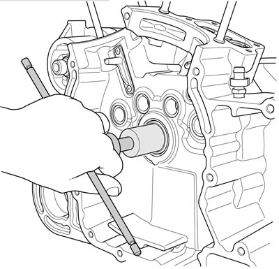
Figure 3-120. Line reaming pinion shaft bushing
3. Turn reamer clockwise through bushing in gearcase cover until reamer bottoms. Then give reamer one complete clockwise turn to size the bushing. Continue turning reamer clockwise while extracting reamer from bushing.
4. Separate gearcase cover from right crankcase. Inspect bushing for proper pinion shaft fit. Repeat line reaming operation if necessary.
Warning! Compressed air can pierce the skin and flying debris from compressed air could cause serious eye injury. Wear safety glasses when working with compressed air. Never use your hand to check for air leaks or to determine air flow rates.
5. Remove pilot from right crankcase roller race. Thoroughly clean gearcase cover, removing all metal chips/shavings. Blow out all bushing bores and oil passages using low pressure compressed air.