Then disassemble top end of engine. See 3.13 TOP END OVERHAUL: DISASSEMBLY, Cylinder Heads and 3.13 TOP END OVERHAUL: DISASSEMBLY, Cylinder and Piston.
Thoroughly clean area around gearcase cover and tappets. Blow loose dirt from crankcase with low pressure compressed air.
The oil pump design and function differs between XL models and the XR 1200X. See 3.6 ENGINE LUBRICATION SYSTEM.
Oil pump: XL models
1. Remove oil pump feed and return hoses. Mark hoses for later installation. Discard hose clamps.
2. See Figure 3-104. Carefully remove two screws (2) that secure pump to crankcase. Pump will drop with screws removed. Discard mounting gasket.
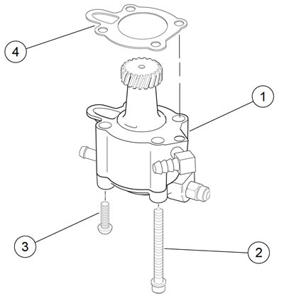
Figure 3-104. Oil pump: XL models: 1. Oil pump; 2. Screw w/ washer (2); 3. Screw, Torx (2); 4. Gasket
3. If oil pump requires repair, see 3.20 OIL PUMP: XL MODELS.
Tappets
1. See Figure 3-105. Remove screw (1).
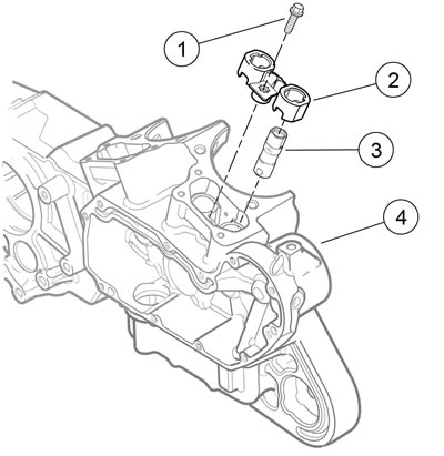
Figure 3-105. Tappet components: 1. Screw (2); 2. Anti-rotation device (2); 3. Tappet (4); 4. Right crankcase
2. Remove anti-rotation device (2). Tag anti-rotation device for location (front/rear cylinder) as it is removed.
3. Remove tappet (3). Tag tappet for location (front/rear cylinder) and function (intake/exhaust) as it is removed. This will simplify installation.
4. Repeat previous steps for other cylinder.
5. Place tappets in clean plastic bags to keep out dust, dirt and debris.
Cam gear end play
Note. Gauge cam gear end play with the tappets removed.
1. Rotate the crankshaft until the lobe of the cam gear is pointing toward the tappet guide bore.
2. With a flat blade screwdriver, gently pry the cam gear toward the gearcase cover.
3. Gauge the gap between the case bushing and the cam gear shaft thrust face.
4. Compare the gauge size to the cam gear end play specifications. Refer to Table 3-14.
Gearcase cover and cam gears: XL models
Warning! Compressed air can pierce the skin and flying debris from compressed air could cause serious eye injury. Wear safety glasses when working with compressed air. Never use your hand to check for air leaks or to determine air flow rates.
1. Remove any parts that will interfere with gearcase disassembly.
2. Remove inner rocker cover to remove valve spring pressure from the camshafts. See 3.22 BOTTOM END OVERHAUL: ASSEMBLY, Cam Gears and Gearcase Cover: XL Models.
3. Measure cam gear end play and record measurements. See 3.17 BOTTOM END OVERHAUL: DISASSEMBLY, Cam Gear End Play.
4. Place a pan under gearcase to collect oil.
Note. Never pry cover off. Tap lightly with a rawhide hammer.
5. See Figure 3-106. Remove cover screws (1) and cover (2). Discard old gasket (3).
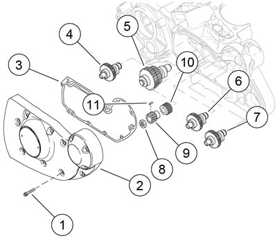
Figure 3-106. Gearcase cover and cam gears: 1. Fastener; 2. Cover; 3. Gasket; 4. Rear exhaust cam; 5. Rear intake cam; 6. Front intake cam; 7. Front exhaust cam; 8. Nut; 9. Pinion gear; 10. Oil pump drive gear; 11. Shaft key
6. Remove cam gears (4, 5, 6 and 7). Mark each component for installation.
Note. Nut is secured by LOCTITE 262 HIGH STRENGTH THREADLOCKER AND SEALANT (red) on the nut threads.
7. Remove nut (8). Slide pinion gear (9) and oil pump drive gear (10) off pinion shaft.
Oil pump housing/gearcase cover and cam gears: XR 1200X
The oil pump is integrated into the gearcase cover. Oil pump rotors can be removed with gearcase cover in place. It is not necessary to remove the oil pump rotors to remove the gearcase cover.
Warning! Compressed air can pierce the skin and flying debris from compressed air could cause serious eye injury. Wear safety glasses when working with compressed air. Never use your hand to check for air leaks or to determine air flow rates.
1. Remove any parts that will interfere with gearcase disassembly.
2. Remove inner rocker cover to remove valve spring pressure from the camshafts. See 3.13 TOP END OVERHAUL: DISASSEMBLY.
3. Measure cam gear end play and record measurements. See 3.17 BOTTOM END OVERHAUL: DISASSEMBLY, Cam Gear End Play.
4. Place a pan under gearcase to collect oil.
Note. Never pry cover off. Tap lightly with a rawhide hammer.
5. See Figure 3-107. Remove cover screws (1) and remove cover (2). Discard old gasket.

Figure 3-107. Oil pump cover: XR 1200X: 1. Fastener (9); 2. Cover
6. See Figure 3-108. Remove rigid lines (1) and vent hose (2) from gearcase cover. Mark lines and hoses for later installation. Discard hose clamps. See 3.12 PRECISION COOLING SYSTEM: XR 1200X, Oil Pump Lines.

Figure 3-108. Gearcase cover and oil pump: XR 1200X: 1. Rigid lines; 2. Vent hose; 3. Check valve screws (2); 4. Oil pump cover screw (6); 5. Oil pump cover; 6. Gearcase cover fastener (3)
7. Remove two check valve housing screws (3).
8. Remove six screws (4) and remove oil pump cover (5). Discard O-rings.
9. Remove three fasteners (6). Loosely install oil pump cover to prevent the gerotors from falling out unexpectedly.
Note. Never pry gearcase cover off. Tap lightly with a rawhide hammer.
10. Carefully remove gearcase cover. Discard old gasket.
Note. Repair the oil pump if required. See 3.21 OIL PUMP: XR 1200X.
11. See Figure 3-109. Remove cam gears (1, 2, 3, and 4). Carefully mark each component to verify correct installation.

Figure 3-109. Cam gears: XR 1200X: 1. Rear exhaust cam gear; 2. Rear intake cam gear; 3. Front intake cam gear; 4. Front exhaust cam gear; 5. Nut; 6. Pinion gear; 7. Spacer
Note. Nut (5) is secured by LOCTITE 262 HIGH STRENGTH THREADLOCKER AND SEALANT (red).
12. Remove nut (5). Slide pinion gear (6) and spacer (7) off pinion shaft.
13. Remove oil pump cover. Mark rotors with a permanent marker to identify outer surfaces. Remove rotors from housing.
Crankcase
Split crankcase
1. Remove clutch and primary drive components. See 5.4 PRIMARY DRIVE AND CLUTCH: XL MODELS.
2. Remove starter motor. See 6.10 STARTER.
3. Mount crankcase assembly in engine stand. Position crankcase so that it is tilted at a 45 degree angle, right side down.
Caution! Do not rotate right crankcase half in engine stand such that flywheel sprocket shaft is facing down. The flywheel assembly can fall out, resulting in parts damage or moderate injury.
Note. XR 1200X: See Figure 3-110. The fastener between the cylinders is a double headed bolt (2).

Figure 3-110. Crankcase fasteners: 1. Long fastener: left side; 2. XR 1200X: double-headed long fastener; 3. Short fastener: left side; 4. Long fastener: right side
4. Remove 11 long fasteners (1, 2) and four short fasteners (3) from left side of crankcase assembly.
5. Remove two fasteners (4) from right side of crankcase assembly.
6. See Figure 3-111. Tap crankcase gently with rawhide mallet to loosen and separate the halves. Remove left crankcase assembly with transmission.
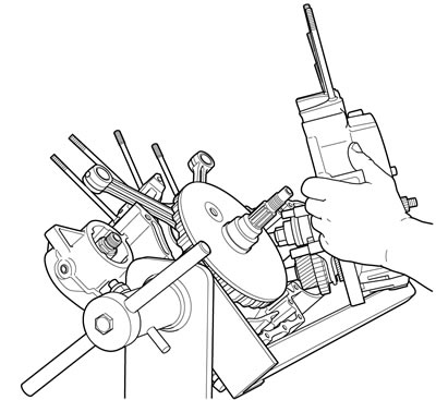
Figure 3-111. Separating crankcase halves
Note. Flywheel assembly slides off left main bearing by hand. No tools are required for this operation.
7. See Figure 3-112. Remove the flywheel assembly from right crankcase.
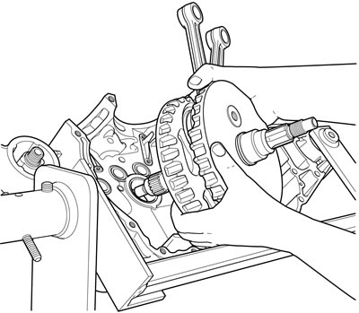
Figure 3-112. Removing flywheels from right crankcase
8. Remove transmission assembly from left crankcase. See 5.9 TRANSMISSION REMOVAL AND DISASSEMBLY.
Piston oil jets
1. See Figure 3-113. Remove two TORX screws (3) from each piston oil jet assembly (2) to free piston oil jets from right crankcase (1).
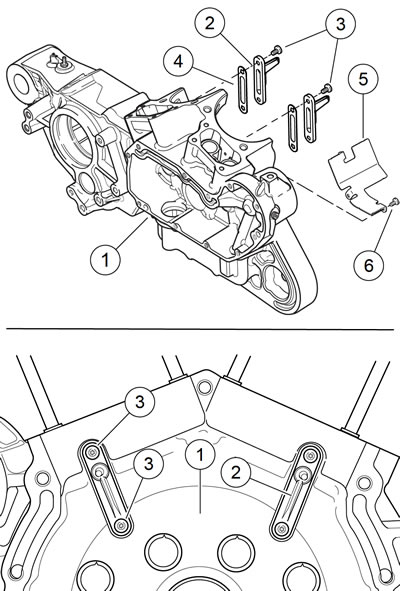
Figure 3-113. Piston oil jet assemblies: 1. Right crankcase; 2. Piston oil jet (2); 3. Screw (4); 4. Gasket (2); 5. Oil deflector plate (XR 1200X); 6. Screw (3) (XR 1200X)
2. Remove piston oil jets and gaskets (4) from right crankcase. Discard gaskets.
3. XR 1200X: Remove three screws (6) and oil deflector plate (5).
Removing cylinder base studs
If cylinder base studs require replacement, proceed as follows.
1. Thread a 3/8-16 nut onto cylinder base stud.
2. Thread a second nut onto stud until it contacts the first nut.
3. Tighten nuts against each other.
4. Placing wrench on first (lower) nut installed, remove stud from cylinder deck.
5. Loosen nuts and remove from cylinder base stud.
