| PART NUMBER | TOOL NAME |
| HD-33446-86 | TORQUE PLATE BOLTS |
| HD-33446-B | CYLINDER TORQUE PLATES |
1. Soak cylinder and piston in an aluminum-compatible cleaner/solvent until deposits are soft. Clean with a brush. Blow off loosened carbon and dirt particles. Wash in solvent.
Warning! Compressed air can pierce the skin and flying debris from compressed air could cause serious eye injury. Wear safety glasses when working with compressed air. Never use your hand to check for air leaks or to determine air flow rates.
2. Clean oil passage in cylinder with low pressure compressed air.
3. Clean piston ring grooves with a piece of compression ring ground to a chisel shape.
4. Inspect piston pin to see that it is not pitted or scored.
5. Check piston pin bushing to see that it is not loose in connecting rod, grooved, pitted or scored.
- a. A piston pin properly fitted to upper connecting rod bushing has a 0.00125-0.00175 in (0.0317-0.0444 mm) clearance in bushing.
- b. If piston pin-to-bushing clearance exceeds 0.002 in (0.0508 mm), replace worn parts. See 3.15 CYLINDER AND PISTON, Connecting Rod Bushings.
6. Clean piston pin lock ring grooves.
7. Inspect piston and cylinder for cracks, burnt spots, grooves and gouges.
Note. Check connecting rod for up and down play in lower bearings. When up and down play is detected, replace flywheel and connecting rod assembly.
Checking gasket surface
Note. Replace the cylinder and piston if either cylinder gasket surface does not meet specification.
1. See Figure 3-72. Check that cylinder top (head) gasket surface is flat within 0.006 in (0.15 mm).
- a. Lay a straight edge across the surface.
- b. Insert a feeler gauge between the straightedge and the gasket surface.

Figure 3-72. Checking gasket surfaces
2. Check that the cylinder base gasket surface is flat within 0.008 in (0.20 mm).
- a. Lay a straightedge across the surface.
- b. Insert a feeler gauge between the straightedge and the gasket surface.
Measuring cylinder bore
1. See Figure 3-73. Remove any burrs from the cylinder gasket surfaces.
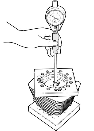
Figure 3-73. Measuring cylinder bore
2. Install a head and base gasket and CYLINDER TORQUE PLATES (Part No. HD-33446-B) and TORQUE PLATE BOLTS (Part No. HD-33446-86). Tighten in the cylinder head torque sequence. See 3.16 TOP END OVERHAUL: ASSEMBLY, Cylinder Head.
Note. Torque plates simulate operating conditions. Without torque plates, measurements vary as much as 0.001 in (0.025 mm).
3. Take cylinder bore measurement in ring path, starting about 1/2 in (13 mm) from top of cylinder, measuring from front to rear, and then side to side. Record readings.
4. Measure at top, center and bottom of the ring path. Record readings. Determine if the cylinder is out-of-round, tapered or bulged. Refer to Table 3-31.
Table 3-31. Cylinder bore service wear limits
| BORE SIZE | XL 883 | XL 1200* | ||
| in | mm | in | mm | |
| Standard bore | 3.0035 | 76.289 | 3.5008 | 88.920 |
| 0.005 in (0.13 mm) Oversize | 3.0078 | 76.398 | 3.5050 | 89.027 |
| 0.010 in (0.25 mm) OS bore | 3.0128 | 76.525 | 3.5100 | 89.154 |
* XR 1200X: Oversized pistons are not available. Replace piston and/or cylinder if exceeds wear limits.
Note. If piston clearance exceeds service limit, cylinders should be bored and honed to next standard oversize. Fit the cylinder with the oversized piston and rings. Do not fit piston tighter than 0.0007 in (0.018 mm). See 3.2 SPECIFICATIONS.
Measuring piston to cylinder fit
Notes:
- This measurement is heat sensitive. Both piston and cylinder must be at room temperature. Holding the piston in your hand for too long can cause measurements to vary by as much as 0.002 in (0.051 mm).
- See Figure 3-74. The measurement is taken on bare aluminum to avoid measuring errors. An oval-shaped opening in the coating is present on each side of the piston for placement of the micrometer.
- See Figure 3-75. The oval openings are too small for a standard flat anvil micrometer. Use a 3-4 inch blade or ball anvil style micrometer, or a 4-5 inch micrometer with spherical ball anvil adapters.
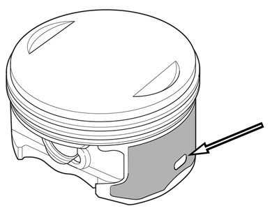
Figure 3-74. Measurement area
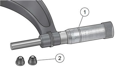
Figure 3-75. Micrometer with anvil adapters: 1. 4-5 inch micrometer; 2. Spherical ball anvil adapter (2)
1. Measure the piston skirt at the oval openings. Transfer that measurement to a dial bore gauge.
Note. Install the torque plates on the cylinder.
2. Mark the top, middle and bottom of the piston ring travel zone with a marker. Measure at markings in cylinder parallel and perpendicular to crankshaft.
3. Replace piston and/or cylinder if running clearance exceeds 0.003 in (0.076 mm).
Boring and honing cylinder
1. The cylinder must be bored with gaskets and torque plates attached. Bore the cylinder to 0.003 in (0.08 mm) under the desired finished size.
Note. With the torque plates installed, hone the cylinder from the crankcase end of the cylinder.
2. Use a 280 grit rigid hone followed by a 240 grit flexible ball hone to hone the cylinder. Work for a 60 degree crosshatch pattern.
Final cylinder bore sizes are measured after honing. Refer to Table 3-32.
Notes:
- When cylinder requires boring over 0.010 in (0.25 mm), replace the cylinder.
- Replace the cylinder if it is scuffed or grooved.
- Use the original piston if cylinder bore was not changed, Replace the rings. Hone the cylinder walls with a No. 240 grit flexible ball hone.
Notice: Failure to remove all abrasive particles may result in premature cylinder, piston and ring wear and engine failure.
3. Thoroughly wash the cylinder bore with liquid dishwashing soap and warm water to remove all abrasive particles and residual grit. Continue cleaning until a clean cloth shows no remaining dirt or debris.
Warning! Compressed air can pierce the skin and flying debris from compressed air could cause serious eye injury. Wear safety glasses when working with compressed air. Never use your hand to check for air leaks or to determine air flow rates.
4. Hot rinse the cylinder. Dry with moisture free low pressure compressed air.
5. Immediately apply a thin film of clean engine oil to a clean white paper towel and thoroughly wipe the inside of the cylinder.
Note. After wiping the cylinder with a clean, oiled paper towel, the towel will be dark with contamination. Repeat this process using a new lightly oiled paper towel each time until the towel remains white. The cylinder is now clean.
6. With the cylinder at room temperature, check the piston clearance in the cylinder in which the piston will run.
Table 3-32. Cylinder final bore sizes
| BORE SIZE | XL 883 | XL 1200** | ||
| in | mm | in | mm | |
| Standard bore* | 3.0005 | 76.213 | 3.4978 | 88.844 |
| 0.005 in (0.13 mm) OS bore | 3.0048 | 76.323 | 3.502 | 88.95 |
| 0.010 in (0.25 mm) OS bore | 3.0098 | 76.449 | 3.507 | 89.08 |
*All bore sizes + 0.0002 in (0.00508 mm)
**XR 1200X: Oversized pistons are not available. Replace piston and/or cylinder if exceeds wear limits.
Fitting piston rings
See Figure 3-76. Piston rings are of two types: compression and oil control. The two compression rings are positioned in the two upper piston ring grooves. The dot on the second compression ring must face upward. Ring sets are available to fit standard and oversize pistons.
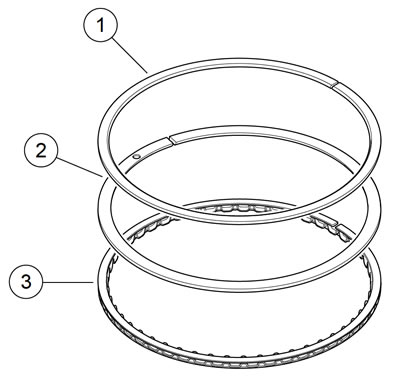
Figure 3-76. Piston rings: 1. Top ring: install either side up; 2. Second ring: install dot toward top; 3. Oil control rings
Piston ring sets must be properly fitted to piston and cylinder:
1. See Figure 3-77. Place piston in cylinder about 1/2 in (13 mm) from top. Set ring to be checked inside cylinder, squarely against piston. Remove piston and check ring end gap with thickness gauge. See 3.2 SPECIFICATIONS.

Figure 3-77. Measuring ring end gap
Notes:
- Always deglaze or hone the cylinder before installing new rings.
- Always use new piston rings. Piston rings take a set and must not be reused.
- Replace a ring if the end gap exceeds specification. See 3.2 SPECIFICATIONS.
- If end gap is under specification, file the ring gap. Insufficient ring gap can cause ring breakage, cylinder scuffing or piston seizure.
- Ring end gap specifications are applicable to rings for oversized pistons.
Warning! Compressed air can pierce the skin and flying debris from compressed air could cause serious eye injury. Wear safety glasses when working with compressed air. Never use your hand to check for air leaks or to determine air flow rates.
2. Blow debris from piston oil drain holes and ring grooves with low pressure compressed air. Apply clean engine oil to piston ring grooves.
3. See Figure 3-78. Install oil control ring expander spring. Make sure ends of spring point upward. Spiral bottom oil control ring into space in ring groove below expander spring. Position oil control ring gap 90 degrees from gap in expander spring. Spiral top oil control ring into space in ring groove above expander spring. Position oil control ring gap 180 degrees from gap in bottom oil control ring.
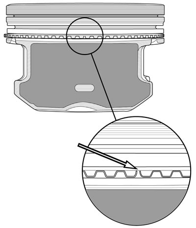
Figure 3-78. Installing oil control ring expander spring (typical)
4. See Figure 3-79. Use a piston ring expander tool to slip compression rings over piston into their respective grooves. Install second compression ring first, then top compression ring. Be extremely careful not to over expand or twist rings, or damage piston surface when installing rings.
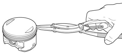
Figure 3-79. Installing piston rings
Note. Install second compression ring with dot towards top of piston.
5. See Figure 3-80. Position rings so end gaps of adjacent rings are a minimum of 90 degrees apart. Ring gaps are not to be within 10 degrees of the thrust face centerline.
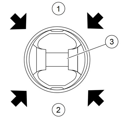
Figure 3-80. Position ring end gaps at arrows
6. See Figure 3-81. Check for proper side clearance with thickness gauge, as shown. See 3.2 SPECIFICATIONS.
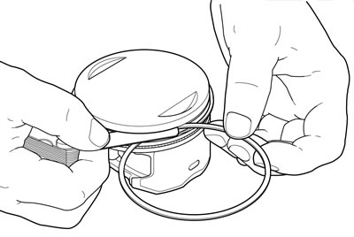
Figure 3-81. Measuring ring clearance in groove
Note. If the ring grooves are clean and the side play is still not correct, replace the rings, the piston or both.
