| PART NUMBER | TOOL NAME |
| B-35758-52A | CUTTER PILOT |
| HD-34751 | VALVE GUIDE CLEANING BRUSH |
| HD-35758-C | NEWAY VALVE SEAT CUTTER SET |
| HD-39786 | CYLINDER HEAD HOLDING FIXTURE |
Notes:
- Check that valve stem to valve guide clearance is correct before refacing. Refer to Table 3-29. If new valve guides must be installed, see 3.14 CYLINDER HEAD, Replacing Valve Guides and complete that task before re facing valve seats.
- This procedure is not based on the lapping of valves. The end result is an interference fit between the 45 degree valve face and the 46 degree valve seat.
Obtain a new valve if grinding leaves the margin less than 0.0313 in (0.795 mm). A valve in this condition does not seat normally, burns easily and may crack or cause preignition.
1. Secure cylinder head for servicing.
- a. Thread 12 mm end of CYLINDER HEAD HOLDING FIXTURE (Part No. HD-39786) into cylinder head spark plug hole.
- b. Clamp fixture in vise. Tighten cylinder head onto the fixture to prevent any movement during operation.
- c. Place cylinder head at a 45 degree angle or one that offers a comfortable working position.
2. To determine the correct location of the 46 degree valve seat in the head, measure the width of the valve. Subtract 0.080 in (2.032 mm) from that number.
3. Set your dial caliper to the lesser measurement and lock it down for quick reference. This is the location of your valve seat.
4. Use a permanent magic marker to highlight the valve seat area to be cut. Highlight all three angles. Allow marker to dry.
Notes:
- Clean the cutter blades and cutter pilot. The correct cleaning brush is supplied with the Neway tool set.
- Clean the inside of the valve guide with the VALVE GUIDE BRUSH.
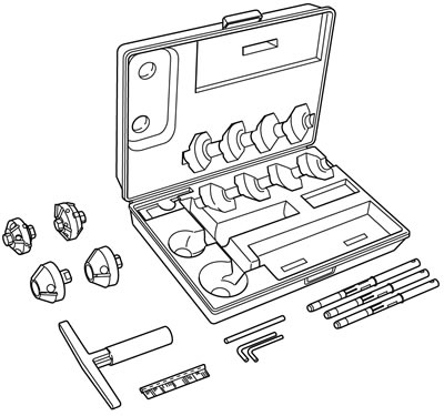
5. See Figure 3-65. Obtain the NEWAY VALVE SEAT CUTTER SET (Part No. HD-35758-C). Select the correct CUTTER PILOT (Part No. B-35758-52A). Securely seat the pilot by pushing down and turning using the installation tool supplied in the tool set.

Figure 3-65. Neway valve seat cutter set (Part no. HD-35758-C)
6. Choose the proper 46 degree cutter (intake or exhaust) and gently slide the cutter onto the pilot. Do not drop the cutter onto the valve seat.
Note. Do not remove any more metal than is necessary.
7. Apply constant pressure. Cut the seat to a uniform finish and to remove pitting.
Notes:
- If the width of the clean-up angle is greater on one side of the valve seat than the other, replace the valve guide.
- After making the 46 degree cut, a groove cut completely around the valve seat indicates worn cutter blades. This condition can be corrected by staggering the blades. Loosen all blades. Move each blade slightly in opposite directions on the cutter. The tool needed to loosen the blades is supplied in the tool set. A permanent magic marker mark every 90 degree will help in determining where new angles are.
8. Lock a dial caliper to the predetermined setting. Measure the 46 degree cut at the outermost edge at the widest point of the circle to determine the next cut.
- a. If the 46 degree cut is too high (towards the combustion chamber), use the 31 degree cutter to lower the valve seat closer to the port.
- b. If the 46 degree cut is too low, use the 60 degree cutter to raise the valve seat or move it away from the port.
Notes:
- Because you are using the top measurement of the valve seat as a reference point, it will usually be necessary to use the 31 degree cutter following the initial 46 degree cut.
- Always highlight the valve seat with the permanent magic marker in order to verify the location of the 46 degree valve seat.
9. If the location of the valve seat is not correct, repeat previous two steps.
10. When you accomplish a complete clean-up of the 46 degree angle and the width is at least 0.062 in (1.575 mm), proceed to the next step.
11. Select the proper 60 degree cutter and gently slide the cutter down the cutter pilot to the valve seat.
12. Remove just enough material to provide an even valve seat width of 0.040-0.062 in (1.016-1.575 mm).
13. Remove cutter and cutter pilot.
14. Repeat the process on any valve seat that needs service.
15. Insert valve in the valve guide and bottom on the valve seat. Position the cylinder head port upwards with slight thumb pressure against the valve. Fill the port with solvent to seal the valve to the seat.
Note. Hold pressure against the valve fora minimum of 10 seconds. If any leakage occurs, examine the valve seat for irregularities or defects and if necessary repeat the above cutting process.
16. Clean valves, cylinder head and valve seats in solvent. Follow up with a thorough wash in hot soapy water.
17. Scrub valve guide bores with VALVE GUIDE CLEANING BRUSH (Part No. HD-34751) and hot, soapy water.
Warning! Compressed air can pierce the skin and flying debris from compressed air could cause serious eye injury. Wear safety glasses when working with compressed air. Never use your hand to check for air leaks or to determine air flow rates.
18. Blow parts dry with low pressure compressed air.

Figure 3-66. Intake and exhaust valve and seat dimensions: 1. Valve seat; 2. Valve; 3. Margin: not less than 0.0313 in (0.795 mm); 4. Valve seat width: 0.040-0.062 in (1.016-1.575 mm)
Replacing valve seats
Replacing a valve seat is a complex operation requiring special equipment. If the valve seat is loose or not fully seated, transfer of heat from the valve will be impaired. The valve seat surface must be flush with or below the head surface. See 3.2 SPECIFICATIONS.
