
Disassembly
1. Remove the cylinder head and liners (see page 3.5).
Caution! The cylinder liners and pistons are made of aluminium alloy and can therefore be easily damaged. Handle the cylinder liner and piston with care, ensuring the internal bore of the liner and the piston skirt are not scratched.
Note: It is not necessary to remove the connecting rods from the crankshaft, but the piston should be at the top of its stroke.
2. Remove the gudgeon pin circlip from one side of the piston.

1. Gudgeon pin circlip
3. Remove the gudgeon pin by pushing the pin through the piston and rod toward the side from which the circlip was removed.
Note: If the gudgeon pin is found to be tight in the piston, check the piston for a witness mark caused by the circlip. Carefully remove the mark to allow the pin to be removed.
4. With the gudgeon pin removed, the piston can be detached from the con-rod.
5. Remove the piston rings.
Note: The rings may be removed using a proprietary piston ring expander tool or, if a tool is not available, carefully spread the ring opening using thumb pressure then push up on the opposite side of the ring to remove it from the piston.
Piston wear check
1. Measure the piston outside diameter, 10 mm up from the bottom of the piston and at 90° to the direction of the gudgeon pin.
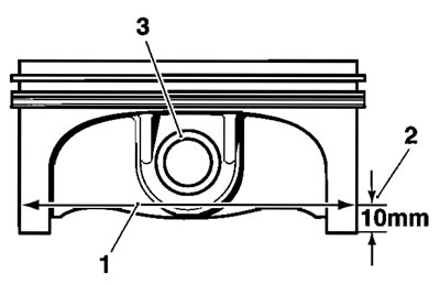
1. Piston outside diameter; 2. Measurement point (10 mm Up The Piston Skirt); 3. Gudgeon pin
| Piston outside diameter at 90° to Gudgeon Pin | |
| All cylinders | 101.561-101.577 mm |
| Service limit | 101.511 mm |
Replace the piston if the measured diameter falls outside the specified limit.
Piston rings/ring grooves
1. Check the pistons for uneven groove wear by visually inspecting the ring grooves.
2. Clean the piston ring grooves.
3. Fit the piston rings to the pistons. Check, using feeler gauges, for the correct clearance between the ring grooves and the rings. Replace the piston and rings if outside the specified limit.

Checking piston ring to groove clearances
| Piston ring/groove clearance | |
| Top - standard | 0.02 - 0.06 mm |
| Top - service limit | 0.16 mm |
| Second - standard | 0.02-0.06 mm |
| Second - service limit | 0.16 mm |
Piston ring gap
Note: Before final assembly the piston ring gap, when fitted in the liner, must first be checked.
1. Place the piston ring inside the liner.
2. Push the ring into the top of the cylinder, using the piston to hold the ring square with the inside of the bore. Continue to push the ring into the bore until the third groove of the piston is level with the top of the liner around its full circumference.
Aligning piston rings using the piston
3. Remove the piston and measure the gap between the ends of the piston ring using feeler gauges.
| Piston ring end gap tolerances | |
| Top - standard | 0.20-0.35 mm |
| Top - service limit | 0.55 mm |
| Second - standard | 0.30-0.50 mm |
| Second - service limit | 0,675 mm |
| Oil control - standard | 0.20-0.70 mm |
| Oil control - service limit | 0.875 mm |
4. If the ring gap is found to be too small, the ring end must be carefully filed until the correct gap is achieved. If the gap is too large, replace the rings with a new set. If the gap remains too large with new rings fitted, both the piston and liner must be replaced.
Piston assembly
1. Clean the piston ring grooves and fit the piston rings to the piston.
Note: The top ring upper surface is marked "N" and can be identified by a chamfer on the inside edge.
The second ring upper surface is marked "2N" but is plain on the inside edge and has a bronze appearance.
All oil control rings can be fitted with either face upward.

Piston ring identification marks
2. Install a new circlip to one side of the piston.
3, Locate the piston to the connecting rod ensuring that the piston direction arrow points to the right hand (exhaust) side of the engine.
1. Piston; 2. Direction arrow
4. Align the small end in the connecting rod with the gudgeon pin hole in the piston.
5. Lubricate the piston, small end and gudgeon pin with clean engine oil and fit the gudgeon pin from the opposite side to the installed circlip.
6. Fit a new circlip to the remaining location in the piston then check that both are correctly installed. Rectify if necessary.
Warning! Re-using the original circlips may cause gudgeon pin detachment resulting in engine seizure, loss of motorcycle control and an accident.
7. The piston ring gaps must be arranged as shown in the diagram below.
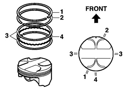
1. Top Ring; 2. Second Ring; 3. Steel Oil Control Rings; 8. Oil Control Ring Expander
Note: The top ring gap should be positioned in the 7 o'clock position, the second ring gap in the 1 o'clock position and the steel oil control ring gaps in the 9 & 3 o'clock positions (one in each position).
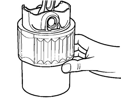
9. Fit the piston into the bottom of the liner using a gentle rocking motion to engage the rings in the bore.
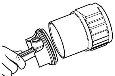
Fitting a piston into a liner
Cylinder wear
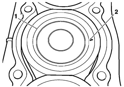
1. Measure the internal diameter of each cylinder liner using an internal micrometer or Mercer gauge. Always check in two places, at 90° to each other, as well as at three heights in the liner.
| Cylinder liner internal diameter | |
| Standard | 101.591-1.609 mm |
| Service limit | 101.659 mm |
Check the diameter at points 1, 2 and 3.

Checking positions for bore wear check (bore shown in section)
2. If any reading is outside the specified limits, replace the liner and piston as an assembly.