Removal
Note. If only replacing brake pads, see 1.10 Brake pads and discs.
Caution! Damaged banjo bolt surfaces will leak when reassembled. Prevent damage to seating surfaces by carefully removing brake line components.
1. See Figure 2-42. Remove banjo bolt (1) and both steel/ rubber washers (2) to detach front brake line (3) from caliper. Discard washers.

Figure 2-42. Front brake caliper mounting: 1. Banjo bolt; 2. Steel/rubber washer; 3. Front brake line; 4. Upper mounting bolt; 5. Lower mounting bolt
2. Remove both upper (4) and lower (5) mounting bolts. Lift caliper upward to remove from brake disc.
3. Repeat for opposite side caliper.
Disassembly
| PART NO. | SPECIALTY TOOL |
| HD-43293 | Brake caliper piston remover |
1. See Figure 2-43. Remove pad pins (10), brake pads (7) and bridge bolts (11) to separate caliper housings (1,8).

Figure 2-43. Front brake caliper: 1. Inside caliper housing; 2. Square seal; 3. Wiper; 4. Piston; 5. Crossover O-ring; 6. Anti-rattle spring; 7. Brake pads; 8. Outside caliper housing; 9. Decal; 10. Pad pin; 11. Bridge bolt; 12. Bleeder valve
2. Remove anti-rattle spring (6). If necessary, remove bleeder valve (12).
3. See Figure 2-45. Remove pistons.
- a. Place BRAKE CALIPER PISTON REMOVER (Part No. HD-43293) between caliper housings.
- b. Insert two bridge bolts (2) and tighten securely.
- c. If the bleeder valve was removed, loosely reinstall or place a gloved finger over the bleeder valve hole on the outside caliper housing.

Figure 2-45. Unseating pistons: 1. Low pressure air hose; 2. Bridge bolt; 3. Brake caliper piston remover (Part No. HD-43293)
Warning! Low pressure compressed air can blow debris into your face and eyes. Always wear eye protection or a face shield when using pressurized air. Failure to take adequate safety precautions could result in death or serious injury.
- d. Apply low pressure compressed air (1) to banjo bolt hole to remove pistons from caliper bores.
- e. Remove bridge bolts and remove tool.
4. See Figure 2-46. Remove and discard both crossover o-rings (1) from inside caliper housing.

Figure 2-46. Crossover о-rings and pistons: 1. Crossover о-rings; 2. Pistons
5. If necessary, wiggle pistons (2) from caliper bores to completely remove.
Caution! Damaged pistons or piston bores will leak when reassembled. Do not use metal objects to remove or install objects from piston bores. Prevent damage to bores by only using a wooden toothpick when servicing calipers.
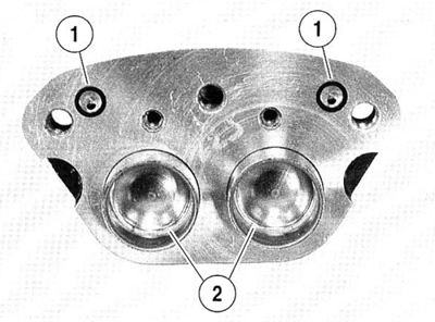
6. See Figure 2-44. Using a wooden toothpick (1), remove a wiper (2) and square seal (3) from each caliper bore. Discard all removed parts.

Figure 2-44. Wipers and square seals
7. Repeat for opposite caliper.
Cleaning, inspection and repair
Warning! Clean brake system components using denatured alcohol. Do not use mineral-base cleaning solvents, such as gasoline or paint thinner. Use of mineral-base solvents causes deterioration of rubber parts that continues after assembly. This may result in improper brake operation which could result in death or serious injury.
1. Clean all parts with denatured alcohol or DOT 5 SILICONE BRAKE FLUID. Do not contaminate with mineral oil or other solvents. Wipe parts dry with a clean, lint free cloth. Blow out drilled passages and bore with a clean air supply. Do not use a wire or similar instrument to clean drilled passages.
2. Carefully inspect all components. Replace any parts that appear damaged or worn.
- a. Check pistons for pitting, scratching or corrosion on face and also on ground surfaces.
- b. Inspect caliper piston bore. Do not hone bore. If bore should show pitting or corrosion, replace caliper.
- c. Always replace wipers, square seals and crossover о-rings after disassembly.
- d. Inspect pad pins for wear and grooving. If wear is more than 0.38 mm (0.015 in.), replace both pins.
3. If decal on outside housing is removed, scrape remaining adhesive from surface with a razor blade.
Warning! Always replace brake pads in complete sets for correct brake operation. Never replace just one brake pad. Failure to install brake pads as a set could result in death or serious injury.
4. Inspect brake pads and brake disc. See 1.10 Brake pads and discs.
5. Repeat for opposite caliper.
Assembly
Caution! Do not use DOT 5 SILICONE BRAKE FLUID for lubrication. Use of DOT 5 brake fluid will result in increased lever travel.
1. Lubricate the following parts prior to assembly using a light coat of G.E. VERSILUBE® #G322 L SILICONE GREASE (marked "Piston Lube") from the service parts kit. All other surfaces must be dry for assembly.
- a. Lubricate nose radius and outside diameter of piston. Apply lube to inside of caliper piston bores.
- b. Apply lube to inside diameter of seals and wipers.
Caution! Damaged piston bores will leak when reassembled. Do not use metal objects to remove or install objects from piston bores. Prevent damage to bores by only using a wooden toothpick when servicing calipers.
2. See Figure 2-44. Install a new square seal (3) and a new wiper (2) into each piston bore.
3. Carefully insert pistons by hand into bores of inside and outside caliper housings. If installation shows resistance, remove piston and check that seals and wipers are properly installed.
4. See Figure 2-46. Place two new crossover o-rings (1) on inside caliper housing.
5. Assemble caliper housings.
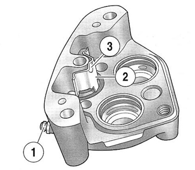
- a. See Figure 2-47. Install bleeder valve (1) on outside caliper housing if removed. Tighten bleeder valve to 9-11 Nm (80-100 in-lbs).
- b. Place outside caliper housing on workbench with decal side down. Install anti-rattle clip (2) in channel with indent (3) facing upwards.
- c. Verify that new crossover о-rings are installed on inside caliper housing.
- d. Mate inside and outside caliper housings using bridge bolts. Place one bridge bolt in the middle hole and one next to the bleeder valve. Loosely install bridge bolts.
- e. Check that anti-rattle spring is still seated between caliper housings.
- f. Tighten bridge bolts to 38-52 Nm (28-38 ft-lbs).

Figure 2-47. Front caliper anti-rattle clip: 1. Bleeder valve; 2. Anti-rattle clip; 3. Indent
Note. See Figure 2-48. The front and rear brake calipers use the same brake pad set.
- On the right side of the vehicle, the pad with two tabs (1) installs on the inboard side of the caliper.
- On the left side of the vehicle, the pad with two tabs (1), installs on the outboard side of the caliper.

Figure 2-48. Brake pad alignment: 1. Two tabs on backing plate; 2. Single square tab on backing plate; 3. Curved portion
6. Insert one set of brake pads into caliper with friction material on pad facing opening for brake disc. Curved portion of pad must face rear of motorcycle when caliper is installed.
7. If necessary, install new pad pins. Pad pins will give an audible click when inserted into inside housing. Tighten both pad pins to 20-23 Nm (180-200 in-lbs).
8. Repeat for opposite caliper.
Note. If pad pins do not fit, check the following:
- You are using a set of pads, not two identical pads.
- Anti-rattle clip orientation matches Figure 2-47.
- Pads must be pushed tight against the anti-rattle clip before the pad pins can be installed.
Installation
1. See Figure 2-42. Attach calipers to fork legs.
- a. Place caliper over brake disc with bleeder valve facing upwards.
- b. Loosely install long upper mounting bolt (4) into top hole on fork leg.
- c. Install short lower mounting bolt (5) into bottom hole on fork leg. Tighten bottom mounting bolt to 38-52 Nm (28-38 ft-lbs).
- d. Final tighten the top mounting bolt to 38-52 Nm (28-38 ft-lbs).
Caution! To avoid leakage, verify that the washers, banjo bolt, brake line and caliper bore are completely clean.
2. Lubricate new steel/rubber washers (2) with DOT 5 SILICONE BRAKE FLUID. Connect the brake line (3) to caliper using two new steel/rubber washers (2) and banjo bolt (1). Tighten to 23-31 Nm (17-23 ft-lbs).
3. Repeat for opposite side caliper.
Warning! Direct contact of DOT 5 SILICONE BRAKE FLUID with eyes may cause eye irritation, swelling, and redness. Avoid eye contact. In case of eye contact flush with large amounts of water and get medical attention. Swallowing large amounts of DOT 5 SILICONE BRAKE FLUID may cause digestive discomfort. If swallowed, obtain medical attention. Use in well ventilated area. KEEP OUT OF REACH OF CHILDREN.
4. Remove cover from front brake master cylinder. Fill master cylinder with D.O.T 5 SILICONE BRAKE FLUID. Verify that fluid level is at FILL LEVEL when the motorcycle is level.
5. Tighten cover screws to 0.7-0.9 Nm (6-8 in-lbs).
Warning! Whenever brake calipers are installed, BEFORE moving motorcycle, you must pump brake fluid until the pistons push the pads against the brake disc. If you don’t pump fluid pressure up again, the brakes will not be available to stop the motorcycle which could result in death or serious injury.
6. Bleed brake system and tighten bleeder valve. See 1.9 Bleeding brakes.
Warning! A plugged or covered relief port can cause brake drag or lockup, which may result in loss of vehicle control which could result in death or serious injury.
7. Verify proper operation of the master cylinder relief port. Actuate the brake lever with the cover removed. A slight spurt of fluid will break the surface if all internal components are working properly.
8. Install gasket and cover on reservoir. Tighten to 0.7-0.9 Nm (6-8 in-lbs).
Warning! After completing repairs or bleeding the system, always test motorcycle brakes at low speed. If brakes are not operating properly or braking efficiency is poor, testing at high speeds could result in death or serious injury.
9. Test brake system.
- a. Turn ignition switch ON. Pump brake hand lever to verify operation of the brake lamp.
- b. Test ride motorcycle. If brakes feel spongy, bleed the system again. See 1.9 Bleeding brakes.
Note. Avoid making hard stops for the first 100 miles (160 km). This allows the new pads to become conditioned to the brake discs.
