General
The clutch is hydraulically actuated. Squeezing the clutch hand lever causes the clutch master cylinder to apply pressure via the clutch fluid in the clutch line to the secondary clutch actuator mounted to the engine right side cover. The secondary clutch actuator piston extends and contacts the clutch release bearing which disengages the clutch.
A bleeder screw at the secondary clutch actuator allows bleeding air from the clutch lines. DOT 5 SILICONE BRAKE FLUID is used in the clutch system.
Check the clutch fluid level in the clutch fluid reservoir on left handlebar. If the sight gauge is dark, the fluid level in the reservoir is above the sight gauge prism and the reservoir is full. If the sight gauge appears clear, the fluid level is below the sight gauge prism and the fluid level should be checked. Fluid level should be level with the internal shelf marked FILL LEVEL with the motorcycle upright.
Caution! DOT 5 SILICONE BRAKE FLUID is used for the hydraulic clutch and is referred to as clutch fluid in this manual. Do not use other types of fluid as they are not compatible.
Removal
1. While holding turn signal locknut underneath clutch lever/master cylinder assembly, unthread mirror (counterclockwise). Remove mirror and turn signal.
2. Remove electrical controls.
Caution! To prevent dirt and other contaminants from entering the master cylinder reservoir, thoroughly clean the cover before removal.
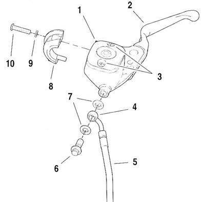
3. See Figure 2-31. Loosen, but do not remove, screws (10) with flat washers (9) that detach handlebar clamp (8) from clutch master cylinder/reservoir.

Figure 2-31. Clutch master cylinder/reservoir: 1. Cover; 2. Clutch hand lever; 3. Cover hold down screws; 4. Banjo fitting; 5. Clutch fluid line; 6. Banjo bolt; 7. Steel/rubber washers; 8. Handlebar clamp; 9. Washer; 10. Clamp screw
4. Loosen both screws (3) on cover (1) to relieve pressure in master cylinder reservoir.
Warning! Be sure NO clutch fluid gets on tires, wheels, or brakes when draining clutch fluid. Traction will be adversely affected which could result in loss of control of the motorcycle and death or serious injury.
Note. Place a large cup under the banjo fitting. Hydraulic fluid will begin draining from the reservoir as the banjo bolt is removed.
Caution! Damaged banjo bolt surfaces will leak when reassembled. Prevent damage to seating surfaces by carefully removing clutch line components.
5. Slowly loosen banjo bolt (6) and allow clutch fluid from reservoir to drain into cup.
Important note. Dispose of clutch fluid in accordance with local regulations.
6. Remove banjo bolt (6) and two steel/rubber washers (7) to disconnect fitting of hydraulic clutch fluid line (5) from clutch reservoir and master cylinder. Discard steel/rubber washers.
Note. To prevent the rest of the clutch fluid from draining from the clutch line and secondary clutch actuator, support the banjo fitting and clutch fluid line upright. Plug the banjo bolt hole with a finger to transfer the assembly to a workbench without spilling clutch fluid.
7. Remove handlebar clamp screws and take clamp and clutch master cylinder/reservoir assembly to a workbench.
Disassembly
Caution! To prevent dirt and other contaminants from entering the master cylinder reservoir, thoroughly clean the cover before removal.
1. Drain additional clutch fluid from master cylinder/reservoir.
2. Remove screws securing master cylinder cover. Remove cover and gasket. Turn housing upside down to remove remaining clutch fluid from reservoir.
Warning! Always wear proper eye protection when removing retaining rings. Use the correct retaining ring pliers. Verify that the tips of the pliers are not damaged or excessively worn. Slippage could propel the ring with force which could cause death or serious injury.
3. Remove retaining ring from pivot pin groove.
Note. To take the piston spring load off the pin and remove the pivot pin, gently force the clutch lever toward the piston (as if operating the clutch).
4. Remove pivot pin through top of housing. Remove and save pivot pin and clutch lever.
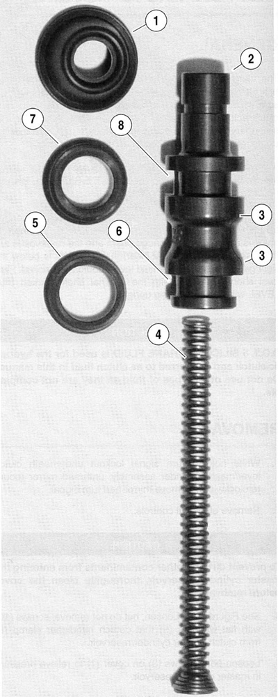
5. See Figure 2-32. Using a toothpick or small screwdriver, gently pry outer edge of piston boot (1) out of piston bore.

Figure 2-32. Clutch master cylinder components: 1. Boot; 2. Piston; 3. Shoulder; 4. Spring; 5. Primary cup; 6. Groove - primary cup; 7. Secondary cup; 8. Groove - secondary cup
6. Remove piston (2) and spring (4).
Warning! Always use denatured alcohol or DOT 5 SILICONE BRAKE FLUID to clean clutch system components. Do not use mineral base solvents (such as gasoline or paint thinner) or deterioration of rubber parts may occur after assembly. Deterioration of components may result in premature brake failure and death or serious injury. Wipe the housing with a lint free cloth. With a clean air supply, blow out drilled passages and bore in the master cylinder housing.
Note. Do not use a wire or sharp instrument to clean drilled oil passages.
7. Inspect cylinder housing bore for scoring, pitting or corrosion. Also check outlet port for damage. Replace housing if necessary.
8. Inspect the cover, sight glass, and gasket for cuts, tears or general deterioration.
Assembly
To rebuild clutch master cylinder, use the components found in the SERVICE PARTS KIT No. 46244-01.
1. See Figure 2-32. Lightly lubricate inside of primary cup (5) and fit over lip on spring end of piston (2) so the closed end (small ID) contacts evenly with the shoulder (3) in primary cup grove (6).
2. Lightly lubricate inside of secondary cup (steep taper from center to outside diameter) (7) and fit over the lip on outboard end of piston (2) so that flared end is open toward the shoulder (3) of the secondary cup groove (8).
3. Install boot (1), large sealing ID first, on piston (2) until seal on smaller ID fits snugly into thin groove in piston.
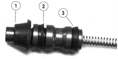
Note. See Figure 2-33. The flared ends of the primary cup and the secondary cup face the spring end of the piston.

Figure 2-33. Assembled cups and piston: 1. Boot in piston groove; 2. Secondary cup flare; 3. Primary cup
4. Using lubricant in SERVICE PARTS KIT (Part No. 46244-01) thoroughly coat outside diameters of primary and secondary cups. Coat master cylinder piston bore.
5. With tapered end out, install spring (4) into opening on inboard side of piston assembly.
6. Align and install piston assembly into bore. Firmly press on flat end of piston, compressing spring, until the entire assembly slides into cylinder bore.
Note. When fitting the piston sealing boot, be careful not to tear, perforate or damage the piston sealing boot.
7. Compress piston until it is even with the end of bore. Using a small dull bladed screwdriver or similar tool, gently work around sealing edges of boot until entire circumference of boot is seated in cylinder bore groove.
8. If cover gasket and/or sight glass replacement is necessary. Proceed as follows:
- a. From inboard side, push sight glass toward top of cover until free.
- b. Pull rubber gasket from cover.
- c. Fit nipple of new gasket into hole of cover aligning gasket and cover thru holes.
- d. From bottom of gasket, push flat end of sight glass through nipple until top of glass is flush with top of gasket. Verify that glass is square in bore. If lubrication is necessary, use clean DOT 5 SILICONE BRAKE FLUID.
9. Install cover with gasket on master cylinder reservoir. Install two screws to fasten the cover to reservoir, but do not tighten.
Warning! Always wear proper eye protection when installing retaining rings. Use the correct retaining ring pliers. Verify that the tips of the pliers are not damaged or excessively worn. Slippage could propel the ring with force which could cause death or serious injury.
10. To install existing clutch hand lever, install clutch hand lever, pivot pin, and a new retaining ring.
11. To install a replacement clutch hand lever, use SERVICE PARTS KIT No. 46243-01. See 2.14 Clutch hand lever.
Installation
1. See Figure 2-31. Attach master cylinder/reservoir to handlebars with handlebar clamp (8). Orient lever to rider position and tighten two clamp screws (10) to 8-9 Nm (71-80 in-lbs).
2. Attach banjo fitting (4) of clutch fluid line to master cylinder with new steel/rubber washers. Install electrical controls.
3. Remove secondary clutch actuator cover and loosen bleeder screw.
4. Fill reservoir with DOT 5 SILICONE BRAKE FLUID. Allow fluid to fill clutch line until a steady flow of clutch fluid flows from bleeder screw. Finger tighten bleed screw.
5. Bleed clutch line. See 1.13 Bleeding clutch fluid line.
6. Verify that fluid level in clutch fluid reservoir is at FILL LEVEL with motorcycle upright.
Note. Clutch fluid volume increases with clutch wear. Do not overfill clutch reservoir.
7. Verify pressure by squeezing clutch hand lever.
8. Tighten fasteners as follows:
- a. Banjo bolt (6) to 23-31 Nm (17-23 ft-lbs).
- b. Bleeder screw to 9-11 Nm (80-100 in-lbs).
- c. Reservoir cover screws to 0.7-0.9 Nm (6-8 in-lbs).
- d. Secondary clutch actuator cover mounting bolts to 6-10 Nm (53-89 in-lbs).
Warning! Check for proper turn signal lamp operation before riding motorcycle. Visibility is a major concern for motorcyclists. Failure to have proper lamp operation could result in death or serious injury.
9. Install rear view mirror and turn signals.
10. Test ride motorcycle.
