Removal
1. Remove secondary clutch actuator cover.
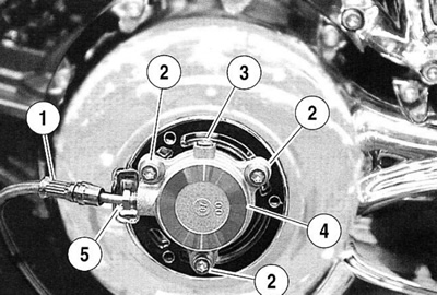
2. See Figure 2-36. Remove mounting bolts (2) holding secondary clutch actuator (4) to clutch cover.

Figure 2-36. Secondary clutch actuator installed: 1. Clutch fluid line; 2. Mounting bolts; 3. Bleeder screw; 4. Secondary clutch actuator; 5. Flare nut
Warning! The piston in the secondary clutch actuator is under pressure. Squeezing the clutch hand lever could push the piston out of its housing with sufficient force to cause death or serious injury.
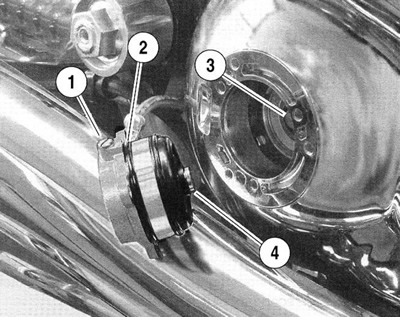
3. See Figure 2-37. Inspect o-ring (2). Replace if necessary and re-install actuator.

Figure 2-37. Secondary clutch actuator: 1. Bleeder screw; 2. O-ring; 3. Clutch release bearing; 4. Secondary clutch actuator piston
Important note. Dispose of clutch fluid in accordance with local regulations.
4. See Figure 2-36. If condition indicates replacement of secondary actuator:
- a. Place a suitable container under secondary clutch actuator (4). Loosen flare nut (5) and allow clutch fluid to drain from clutch line (1).
- b. Remove flare nut and remove actuator.
- c. Remove bleeder screw and drain remaining clutch fluid.
Disassembly
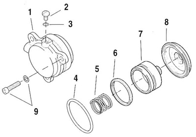
1. See Figure 2-38. Remove o-ring (3) from bleeder screw (2).

Figure 2-38. Secondary clutch actuator components: 1. Secondary clutch actuator housing; 2. Bleeder screw; 3. Bleeder screw o-ring; 4. O-ring; 5. Spring; 6. Seal; 7. Piston; 8. Boot; 9. Mounting bolts and washers
2. Pull off boot (8), piston (7), seal (6), and spring (5) from housing (1). Slip o-ring (4) off housing.
3. Clean with denatured alcohol or DOT 5 SILICONE BRAKE FLUID, only.
4. Use air hose to clean inlet and bleeder ports.
5. Inspect cylinder housing bore for scoring, pitting or corrosion. Inspect inlet and bleeder ports. Replace housing if necessary.
Assembly
1. See Figure 2-38. Coat cylinder bore, piston, o-ring, boot, and bleeder screw with lubricant from service kit.
2. Orient a new seal (6) with square split lip toward rider side of actuator and fit to piston (7).
3. Insert spring into cylinder bore and insert piston into cylinder bore. Compress and guide seal lip as piston is pressed into bore.
4. Install a new o-ring (4) into groove at base of secondary clutch actuator housing (1).
5. Fit boot (8) to piston (7) and push edge of boot over machined lip around housing (1).
6. Fit new o-ring (3) to bleeder screw (2) and loosely install into housing.
Installation
1. Install clutch fluid line flare nut to secondary clutch actuator. Tighten to 9-13 Nm (80-115 in-lbs).
2. Loosen bleeder screw.
Warning! Be sure NO clutch fluid gets on rear tire, wheel or brakes when adding clutch fluid. Traction will be adversely affected which could result in loss of control of the motorcycle and death or serious injury.
Warning! Do NOT allow foreign matter to enter the clutch master cylinder reservoir. Dirt or debris in the reservoir may cause improper operation of the clutch and equipment damage.
Warning! Direct contact of DOT 5 SILICONE BRAKE FLUID with eyes may cause eye irritation, swelling, and redness. Avoid eye contact. In case of eye contact flush with large amounts of water and seek medical attention immediately. Swallowing large amounts of DOT 5 SILICONE BRAKE Fluid may cause digestive discomfort. If swallowed, seek medical attention immediately. Use in well ventilated area. KEEP OUT OF REACH OF CHILDREN.
Warning! The piston in the secondary clutch actuator is under pressure. Squeezing the clutch hand lever could force the piston out of its housing with sufficient force to cause death or serious injury.
3. Fill reservoir with DOT 5 SILICONE BRAKE FLUID. Allow fluid to fill clutch line until a steady flow of clutch fluid flows from bleeder screw. Tighten bleeder screw.
Note. When filling an empty clutch fluid line, a Snap-on BASIC VACUUM BRAKE BLEEDER with a fitting that mates to the bleeder screw threads can be used to initially draw the fluid down the clutch line with little or no air in the line.
4. Bleed clutch fluid line. See 1.13 Bleeding clutch fluid line.
5. Tighten fasteners as follows:
- a. Banjo bolt to 23-31 Nm (17-23 ft-lbs).
- b. Bleeder screw to 9-11 Nm (80-100 in-lbs).
- c. Reservoir cover screws to 0.7-0.9 Nm (6-8 in-lbs).
6. Determine sufficient piston travel.
Note. Insufficient piston travel may indicate a fluid or pressure leak somewhere in the actuator, clutch fluid line, or clutch master cylinder.
7. Press secondary clutch actuator into its mounting flange on crankcase cover. Install fasteners and tighten to 10 Nm (89 in-lbs).
8. Install secondary clutch actuator cover. Tighten to 6-10 Nm (53-89 in-lbs).
