General
The voltage regulator is mounted between the front frame downtubes, directly above the radiator.
Note. The voltage regulator cannot be repaired. Replace the unit if it fails.
Removal
1. Unlock and open seat.
2. Remove the airbox assembly. See 1.4 Airbox and air filter.
Caution! See Figure 8-12. Cover the injector intakes with duct tape to prevent contaminates/objects from falling down the injector bore. Do NOT use shop cloths or objects that could damage the injector butterflies.

Figure 8-12. Airbox removed, injector intakes protected
3. Remove maxi-fuse. See 8.5 Maxi-fuse.
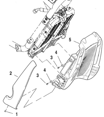
4. See Figure 8-13. Remove the mounting fasteners (1) and left and right radiator trim covers (2).

Figure 8-13. Removing radiator covers: 1. Fastener @ 3-4 Nm (26-35 in-lbs); 2. Radiator trim cover; 3. Fastener (4) 4.1 -6.8 Nm (36-60 in-lbs); 4. Washer (4); 5. Radiator cover
Note. Before removing voltage regulator wires, carefully note wire routing. In particular, pay close attention to locations of cable straps that must be replaced.
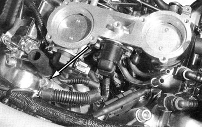
5. See Figure 8-14. Remove fastener, washer and voltage regulator ground wire from front cylinder head. Cut and remove any cable straps securing ground wire to frame.

Figure 8-14. Voltage regulator grounding fastener
6. See Figure 8-15. Remove voltage regulator 3-wire harness connector clip from left side of radiator cover. Disconnect voltage regulator connector [46B] from alternator connector [46А].

Figure 8-15. Voltage regulator-to-alternator connector [12]
7. Remove all other wiring harness cable straps and clips attached to left side of radiator cover.
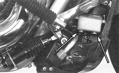
8. See Figure 8-16. Pull rear brake master cylinder reservoir straight away from its mounting slots in right side of radiator cover.

Figure 8-16. Rear brake master cylinder reservoir mounting slots
9. See Figure 8-13. Remove mounting fasteners (3), washers (4) and radiator cover (5).
10. Disconnect voltage regulator connector [77B] from maxifuse connector [77А]. This connector is located on the front of the radiator near the top.
11. Remove two fasteners securing voltage regulator to frame and remove voltage regulator from vehicle.
Installation
1. Attach new voltage regulator to frame with two mounting fasteners.Tighten to 6-10 Nm (53-88 in-lbs).
2. Route voltage regulator wire harnesses.
- a. Route ground wire along left top frame tube to mounting fastener on front cylinder head.
- b. Route maxi-fuse wire along top of radiator and plug into connector [77А].
- c. Route three-wire harness along top of radiator and down left side. Plug into alternator connector [46А].
3. See Figure 8-14. Attach voltage regulator ground wire to front cylinder head. Tighten to 16-20 Nm (12-15 ft-lbs).
4. Secure voltage regulator wire harnesses with cable straps at appropriate locations.
5. See Figure 8-13. Attach radiator cover with four fasteners (3) and washers (4). Tighten to 4.1-6.8 Nm (36-60 in-lbs).
6. See Figure 8-16. Press rear brake master cylinder reservoir back into its mounting slots in right side of radiator cover.
7. Reroute wiring harnesses down left side of radiator cover and attach with clips or cable straps as appropriate.
8. See Figure 8-13. Attach left and right radiator trim covers (2) to radiator cover with mounting fasteners (1). Tighten to 3-4 Nm (26-35 in-lbs).
9. Remove duct tape from injector intakes.
10. Install airbox assembly. See 1.4 Airbox and air filter.
11. Turn ignition switch to the FUEL position and close seat. Then turn ignition switch to the LOCK position.
Caution! When closing the seat, make sure the ignition switch is in the FUEL position. If the ignition switch is in any other position when the seat is closed, the seat latch mechanism could be damaged.
12. Replace maxi-fuse. See 8.5 Maxi-fuse.
13. See the VRSCA Electrical Diagnostic Manual and check voltage regulator for proper output.
