
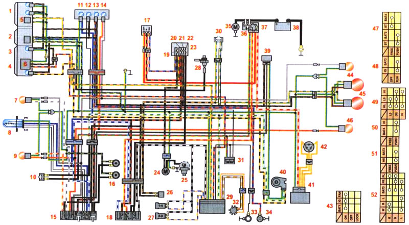
Wiring diagram of the CB400N modification motorcycle (without warning lamp for exceeding the permissible speed): 1 - instrument panel illumination lamps; 2 - coolant temperature gauge; 3 - speedometer; 4 - control lamp of the side stop; 5 - tachometer; c - speed sensor; 7 - front right direction indicator; 8 - headlight lamp; 9 - front left turn signal; 10 - clutch sensor; 11 - high beam control lamp; 12 - neutral control lamp; 13 - oil pressure control lamp; 14 - control lamp of the right direction indicator; 15 - switch for direction indicators, headlights and sound signal; 18 - sound signal; 17 - ignition lock; 18 - emergency engine switch; 19 - fuse (10A) radiator fan; 20 - fuse (10A) headlights; 21 - fuse (10A) circuits of devices, side light, sound signal; 22 - fuse (10A) ignition systems; 23 - fuse block; 24 - fan electric motor; 25 - coolant temperature sensor; 28 - front brake light switch; 27 - ignition coil; 28 - coolant temperature sensor; 29 - engine control unit; 30 - rear brake light switch; 31 - diode; 32 - breaker; 33 - neutral sensor; 34 - oil pressure sensor; 35 - starter; 36 - starter relay; 37 - main fuse (30A); 38 - battery; 39 - direction indicator relay; 40 - side stop sensor; 41 - rectifier; 42 - generator; 43 - ignition switch; 44 - rear right turn signal; 45 - brake signal/side light lamps in the rear light; 48 - rear left turn signal; 47 - starter switch; 48 - engine switch; 49 - headlight switch; 50 - headlight switch; 51 - horn switch; 52 - turn signal switch