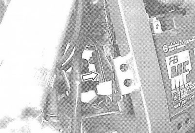
Side stand relay
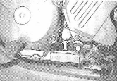
Remove the rear shock absorber expansion tank (section 5-30).
First check for continuity between pins A and B using a tester. Then apply 12V to pins C and D («+» in C and «–» on D) and check continuity again between A and B. If there is no continuity, replace the relay.
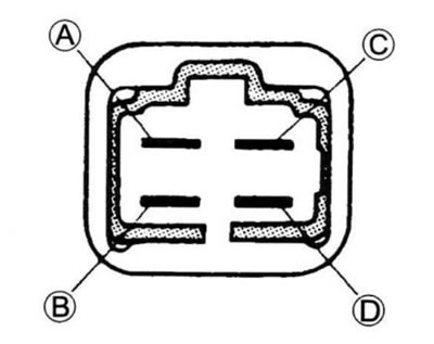
Tool: 09900-25008 – Multitester
Operating mode: Conductivity test
Side stand position indicator
Remove the seat (section 5–3).
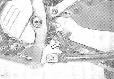
Disconnect the signaling device connector (1).
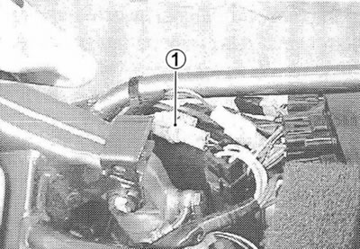
Measure the voltage between the Green and Black/White wires using a tester. See table below.
Tool: 09900-25008 – Multitester
Operating mode: Diode test
| Green («+» dipstick) | Black White («-» dipstick) | |
| ON (Stand raised) | 0.4–0.6 V | |
| OFF (Stand down) | More than 1.4 V (Tester battery voltage) | |
Note. If the tester readings are less than 1.4 V, replace its battery.
Neutral indicator
Section 8–21.
Side stand diode
Remove the chair (section 5–3).
Remove the diode (1).
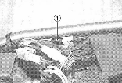
Measure the voltage between the terminals using a tester. See table below.
Tool: 09900-25008 – Multitester
Operating mode: Diode test
| «–» tester probe to: | «+» tester probe to: | ||
| (B), (C) | (A) | ||
| (B), (C) | More than 1.4 V (Tester battery voltage) | ||
| (A) | 0.4–0.6 V | ||
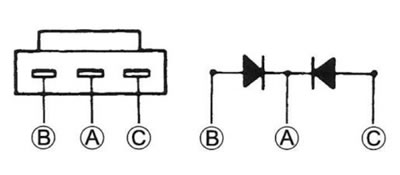
Note. If the tester readings are less than 1.4 V, replace its battery.
Turn signal relay
Remove the headlight cover.
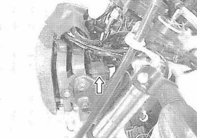
Examination
Before replacing the turn signal relay, check the operation of the turn signal.
If the turn signal does not work, check the lamp, turn signal switch and wire connections.
If the lamp, turn signal switch and wiring are good, the turn signal relay may be faulty, replace it.
Note. Make sure the battery is fully charged.
