
Note: Make sure all connectors are connected properly.
Remove the seat (section 5-3).
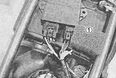
Disconnect the connector with wires from the switch (CDI). Measure the peak voltage on the sensor winding and signal winding as described below.

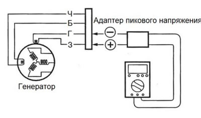
Connect the multitester to the peak voltage adapter as follows.
Sensor winding:
- (+) Probe: Green wire
- (-) Probe: Blue wire
Signal winding:
- (+) Probe: White wire
- (-) Probe: Black wire
09900-25008: multitester
Warning! Before using the multitester and peak voltage adapter, make sure that the actions comply with the instructions for the devices.
Place the gearbox in neutral and turn the ignition key to position «Included».
Squeeze the clutch lever.
Press the starter button and crank the engine for a few seconds, then measure the peak voltage at the sensor winding and the signal winding.
Repeat the above procedure several times and take the highest peak voltage value.
Tester pen installation: Constant voltage
Peak voltage of the sensor winding: not less than 5.0 V
Peak voltage of the signal winding: no less than 1.2 V
Sensor winding | 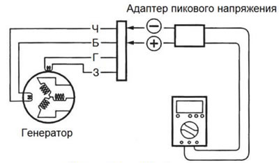
Signal winding |
Resistance of the sensor winding and signal winding
Remove the seat (section 5-3).
Disconnect the generator connector.
Measure the resistance between the wires using a multi-tester. If the resistance does not fall within the specified value, the sensor winding and signal winding must be replaced.
09900-25008: multitester
Tester pen installation: Resistance measurement
Load winding resistance: 390-620 Ohm (Blue - Green)
Signal winding resistance: 0.1-1.2 Ohm (Black White)