MotoInstruction.ru
Mobile
version
Articles
& news
Site
map
Feed
back
Add to
bookmark
English Русский
Aprilia
BMW
Ducati
Harley
Honda
Kawasaki
Suzuki
Triumph
Yamaha
Ducati:
ST series▾
ST2 (1997-2003)
Monster▾
Monster 696 (2007-2014)

Reassembly clutch (Ducati ST2)

  • Main
  • Ducati
  • ST series
  • ST2
  • Engine and systems
  • Transmission
  • Reassembly clutch
0
Before refitting the clutch cover, make sure that it has a seal ring on the crankshaft with relative washer and circlip. When changing the seal ring (1), refit and position the new part as shown in the diagram.

Before refitting the clutch cover, make sure that it has a seal ring on the crankshaft with…


Position the reference bush (2) and the O-ring (3) between the casing and the cover.

Position the reference bush (2) and the O-ring (3) between the casing and the cover.


Fit the seal and the right side cover.

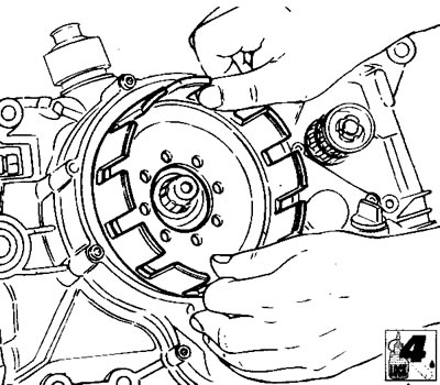
To prevent damage to the seal ring (4) sliding surface, when fitting the clutch cover on the clutch housing gear hub, use the special bush 88700.5665.

To prevent damage to the seal ring (4) sliding surface, when fitting the clutch cover on the clutch…


For correct installation, proceed as follows:


  • insert the bush with the side with the larger diameter in contact with the gear hub;
  • fit the seal ring (A) in the clutch cover, with the closed side facing outwards;
  • lubricate the lips of the seal ring (A) with engine oil;
  • install the clutch cover by guiding the seal ring on the bush;
  • Push it until it is on the gear hub. Remove the bush.

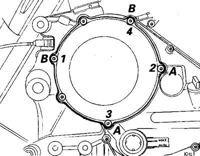
Insert the retaining screws and brackets (5 and 6) with relative spacers and washers as shown in the diagram:

ref.quantitydescription (mm)
A4M6x25 screws
B2M6x35 screws
C1M6x65 screws
D1M6x70 screws

Reassembly clutch


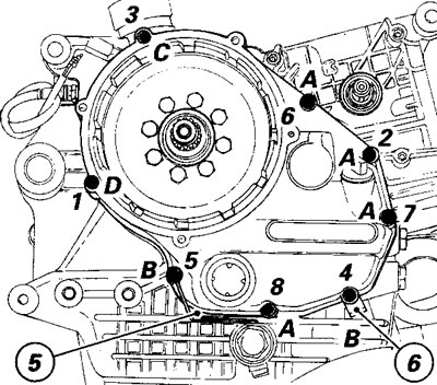
Tighten the retaining screws at the specified torque following the numbered sequence shown in the diagram.

Tighten the retaining screws at the specified torque following the numbered sequence shown in the…


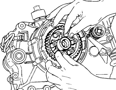
Fit the clutch housing to the gear.

Apply flange sealant under the screw heads and on the threads of the retaining screws, fit them and tighten them, working crossways, at the specified torque value.


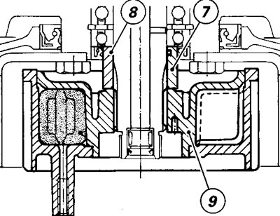
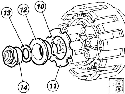
Insert the spacer (7), with lubricated O-ring (8) and the clutch drum (9) with cush drive pads on the primary shaft.

Insert the spacer (7), with lubricated O-ring (8) and the clutch drum (9) with cush drive pads on…


Insert the lubricated O-ring (10) on the end part of the primary shaft and fit the support washer (11).

Insert the lubricated O-ring (10) on the end part of the primary shaft and fit the support washer…


Then insert the bush (12) in the centring pin on the cush drive pad hub and insert the safety washer (13) and nut (14) inside it.

Then insert the bush (12) in the centring pin on the cush drive pad hub and insert the safety…


Secure the clutch drum using service tool 88713.0146 and tighten the retaining nut at the specified torque.


Secure the clutch drum using service tool 88713.0146 and tighten the retaining nut at the specified…


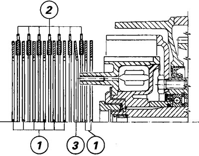
Insert the series of clutch plates (code number 19020013A) in the following order:
  • two driven plates (1) with thickness of 2 mm;
  • a drive plate (2) with thickness of 3 mm;
  • one convex plate (3) with thickness of 1.5 mm, fitted as shown in the diagram;
  • the series of 6 drive plates (2) alternating with 6 driven plates (1);
  • when the last of these is fitted, the pack is complete.

when the last of these is fitted, the pack is complete.


Caution! After refitting the original plate pack or after fitting a new plate pack, check the clutch fluid level in the reservoir.


Insert the control pin in the pusher plate.

Insert the control pin in the pusher plate.


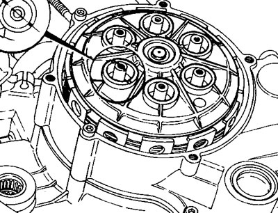
Fit the pusher plate so that the reference on the end of one of the drum pins corresponds with the reference on the sides of the pusher plate hole.

Fit the pusher plate so that the reference on the end of one of the drum pins corresponds with the…


Insert a spring and a cap in each hole and secure the screws at the specified torque.

Position the soundproofing seal and the clutch inspection cover.

Insert the retaining screws as shown in the diagram, following the numbered order:

Insert the retaining screws as shown in the diagram, following the numbered order:


ref.qtydescription (mm)
A2M6x20 screws
B2M6x70 screws

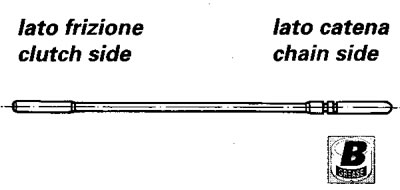
From the left side of the casing, insert the greased control rod with the two O-rings fitted to it. The O-ring side must be on the left.
See this article in russian language
This article has been reviewed: Evgeny Bogomolov
◀ Previous
Ducati ST2 : Transmission
Next ▶

Overhaul gear selector forks
Overhaul selector drum
Shimming the gearbox shaft
Gearbox overhaul
Reassembly gear selector lever
Similar articles about motorcycles of other brands
Clutch — reassembly Suzuki Boulevard M109R (2006-2025)
Exploded view — clutch controls Triumph Rocket III (2004-2018)
Clutch lever Yamaha FZ1 Fazer (2006-2015)
Clutch exploded view Kawasaki ZX6R/ZX600J (2000-2002)
Clutch — disassembly and assembly, replacement of discs and… Honda CB 400 SF (1992-1999)
Link to this article in different formats
TEXTHTMLBB Code
Comments and feedback from visitors
No comments yet, you will be the first!


Add up two numbers: 36 + 33


ST2 (1997-2003) 
  • Information for owner
  • Technical characteristics
  • Maintenance
  • Engine and systems
  • Engine repair
  • Fuel and exhaust system
  • Fuel injection
  • Cooling and lube system
  • Transmission
  • Running gear and frame
  • Frame and hinged elements
  • Wheels and tires
  • Brake system
  • Front suspension and handlebar
  • Rear suspension
  • Electric equipment
  • Equipment and devices
  • Starting and charging system
Aprilia BMW Ducati Harley Honda Kawasaki Suzuki Triumph Yamaha
MotoInstruction.ru © 2021–2025 | Sitemap | Articles | Contacts | Site search | Add to bookmarks | Mobile version