
Disassembly
I. Drain the engine oil (see «Changing engine oil and oil filter»).
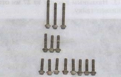
2. Using an 8 mm socket wrench, unscrew the 14 bolts securing the left engine cover.

Attention! The crankcase cover bolts are of different lengths. It is important to remember their location in order to install them in their place during assembly.
3. Remove the cover.
4. To completely disconnect the cover, turn off the generator wiring harness (connector is under the seat) or with a 5 mm hex wrench, unscrew the four screws securing the generator stator to the cover.

5. Using a 10 mm spanner, unscrew the bolt securing the retaining bracket of the generator wiring harness.

6. If the cover gasket is stuck to the planes and torn, we will reprimand the remnants of the old gasket from the mating surfaces of the crankcase and cover.
7. To fix the rotating parts of the power unit, we turn on 1st gear and fix the rear brake pedal in the depressed position, for example, using a piece of rope.
8. Using a 10 mm spanner or socket wrench, unscrew the four bolts securing the release plate.
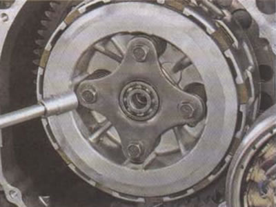
9. Remove the plate assembly with the release bearing.

10. Remove the clutch springs.

11. We examine the springs. If at least one of the springs is deformed or broken, the entire set must be replaced. Using a caliper we measure the height of the springs.
- The nominal free height of the spring is 45.6 mm.
- The minimum free height of the spring is 41.7 mm.
If the height of at least one spring is less than specified or the springs have a difference in height of more than 1 mm. the entire set must be replaced.
Attention!
- It is unacceptable to replace springs one at a time. Springs of different stiffnesses (old and new), installed in one package will cause the discs to skew during operation, which can lead to slippage, uneven wear of the discs, and even their breakage.
- The springs are color-coded for stiffness. When replacing, it is important to ensure that all springs have the same markings.
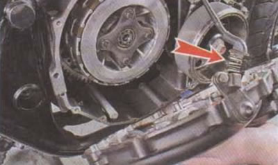
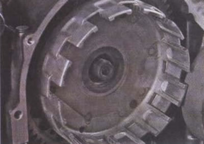
12. We bend the center nut of the clutch basket (indicated by an arrow).

13. Using a 27 mm spanner, unscrew the nut.

14. Remove the clutch thrust disc assembly with two spacer washers (installed on the gear side).
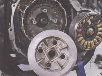
15. We remove the package of disks assembled with the pressure disk from the outer drum.
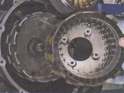
Attention! If the disks are installed back after troubleshooting, it is important not to confuse their relative positions and installation order. The discs rub against each other during operation, and if installed incorrectly, the clutch may begin to slip.
16. Inspect the kit. Steel disks should not have deformations, signs of overheating, especially in the area of the teeth, or other mechanical damage. Friction discs should not have chips, cracks, or gouges. The thickness of the disk should be the same throughout the entire working part.
We measure the thickness of the disks.
- The nominal thickness of the disc is 3.22-3.38 mm.
- Nominal Thrust Disc Thickness (narrow) - 3.42-3.58 mm.
- The minimum disc thickness is 2.90 mm.
- Minimum thrust disc thickness (narrow) - 3.10 mm.
If the thickness of at least one of the discs is less than the minimum allowable, the entire set of discs must be replaced.
Attention! Clutch friction discs are replaced only as a set. It is not allowed to replace individual discs.
17. Check the condition of the clutch basket bearing. If the basket has play on the shaft, rotates with jamming, clicks or strong extraneous noise, the needle bearing must be replaced.
18. Remove the basket from the shaft and replace the needle bearing (the bearing is mounted on the shaft without preload).
Clutch parts
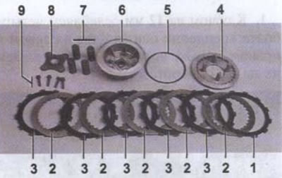
1 - persistent (narrow) friction disc; 2 - steel disk; 3 - friction disc; 4 - pressure disk; 5 - spacer washer of the thrust disk; 6 - thrust disk; 7 - springs; 8 - release plate assembled with release bearing; 9 - mounting bolts
Assembly
We assemble the clutch in the reverse order.
Tighten the central nut to a torque of 80-85 Nm. and we core its edge so that it enters the groove of the shaft.
We tighten the release plate bolts with a torque of 25-30 Nm. Bolts should be tightened crosswise.
After assembly, adjust the clutch actuator (see «Clutch cable - removal and installation, adjustment»).