Removal
Note. Label hardware for location and orientation upon removal.
1. Position motorcycle on a suitable lift.
2. XL models: Remove rear exhaust pipe and muffler. See 4.13 EXHAUST SYSTEM: XL MODELS.
3. XR 1200X: Remove exhaust system. See 4.14 EXHAUST SYSTEM: XR 1200X.
4. Remove rear wheel. See 2.5 WHEELS.
5. Remove rear brake caliper assembly from rear fork. See 2.14 REAR BRAKE CALIPER: XL MODELS or 2.15 REAR BRAKE CALIPER: XR 1200X.
6. Remove screw(s) securing brake line clamp(s) to rear fork.
7. XR 1200X: Remove fasteners securing brake line to left side of rear fork.
8. Remove both shock absorber screws, washers and nuts from rear fork. See 2.24 SHOCK ABSORBERS.
9. Remove rear belt guard and debris deflector. See 2.22 BELT GUARD AND DEBRIS DEFLECTOR.
10. XL Models: Remove rear brake reservoir cover by grasping cover and gently pulling straight out from reservoir. Remove reservoir mounting screw and pull reservoir back out of the way. See 2.13 REAR BRAKE MASTER CYLINDER RESERVOIR.
11. XL Models: Loosen, but do not remove, top mounting screw from left passenger footrest bracket. Remove bottom mounting screw. Move brake hoses and clamp forward slightly to gain access to left rear fork/engine mount bolt.
12. XR 1200X: Remove left and right rider footrests. See 2.42 RIDER FOOT CONTROLS: XR 1200X.
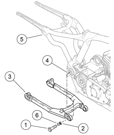
13. See Figure 2-162. Support rear fork (3). Remove rear fork/engine mount bolts (1) and pull fork assembly from frame.

Figure 2-162. Rear fork assembly: 1. Bolt (2); 2. Bearing (2); 3. Rear fork; 4. Pivot shaft; 5. Frame; 6. Retaining ring
Disassembly
| PART NUMBER | TOOL NAME | |
| HD-46281 | BEARING REMOVER/INSTALLER TOOL | |
Note. See Figure 2-162. Remove pivot bearings (2) only if replacement is required.
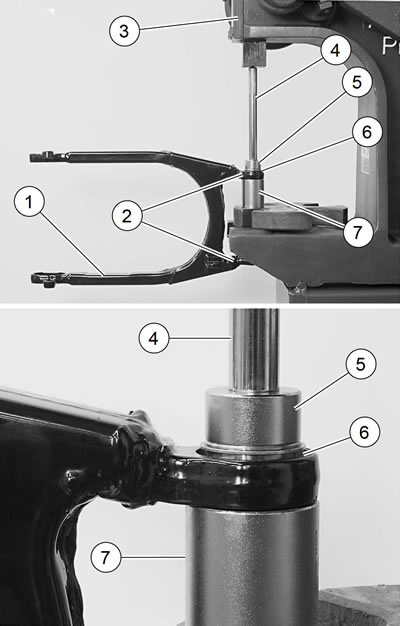
1. See Figure 2-163. Using BEARING REMOVER/INSTALLER TOOL (Part No. HD-46281) (4, 5, 6), carefully press bearing assemblies from fork bearing bosses (2):
- a. Place receiver cup (6) on press bed, with recessed end of cup facing up.
- b. Place rear fork pivot bearing boss (2) over cup as shown in the photo.
- c. Slide pilot (5) through bearing and into receiver cup.
- d. Insert handle (4) through other rear fork pivot bearing boss and bearing, down into pilot.
- e. Engage press ram on end of handle and press bearing out.

Figure 2-163. Removing rear fork pivot bearings: 1. Rear fork; 2. Pivot bearing boss; 3. Press; 4. Handle; 5. Pilot; 6. Receiver cup
2. Turn rear fork over. Press out the opposite pivot bearing.
Cleaning and inspection
1. Clean all components in solvent.
Warning! Compressed air can pierce the skin and flying debris from compressed air could cause serious eye injury. Wear safety glasses when working with compressed air. Never use your hand to check for air leaks or to determine air flow rates.
2. Blow dry with low pressure compressed air.
3. Carefully inspect bearings for wear and/or corrosion. Replace as necessary.
4. See Figure 2-162. Make sure pivot bearing retaining ring (6) is not bent or damaged. If it is, replace it with a new retaining ring.
5. Make sure retaining ring is fully seated in the groove in each bearing (2).
6. Check that rear fork (3) is not bent, twisted or cracked. Replace as necessary.
Assembly
| PART NUMBER | TOOL NAME | |
| HD-46281 | BEARING REMOVER/INSTALLER TOOL | |
1. See Figure 2-162. If necessary, press new bearings (2) into position in rear fork, using BEARING REMOVER/INSTALLER TOOL (Part No. HD-46281):
- a. See Figure 2-164. Place receiver cup (7) on press bed, with recessed end of cup facing up.
- b. Place rear fork pivot bearing boss (2) over cup as shown in the photo.
- c. Place new pivot bearing (6) over pivot bearing boss, with retaining ring side of bearing up.
- d. Slide pilot (5) through new pivot bearing, through pivot bearing boss, and into receiver cup.
- e. Insert handle (4) down into pilot.
- f. Engage press ram on end of handle and press bearing down until retaining ring bottoms out in rear fork pivot bearing boss.

Figure 2-164. Installing rear fork pivot bearings: 1. Rear fork; 2. Pivot bearing boss; 3. Press; 4. Handle; 5. Pilot; 6. Bearing; 7. Receiver cup
2. Turn rear fork over. Press the other pivot bearing into rear fork pivot bearing boss.
Installation
| FASTENER | TORQUE VALUE | |
| Fork, rear, pivot/engine mount bolt | 60-70 ft·lbs | 81.4-95.0 Nm |
| Footrest mount fastener | 45-50 ft·lbs | 61-68 Nm |
| Brake master cylinder reservoir, rear, mounting screw | 20-25 in·lbs | 2.3-2.8 Nm |
1. Slide rear fork assembly into position on motorcycle.
2. See Figure 2-162. Holding rear fork assembly in position, install rear fork/engine mount bolts (1). Tighten to 60-70 ft·lbs (81.4-95.0 Nm).
3. XL Models: Position rear brake hose clamp and left passenger footrest bracket in place. Install lower mounting screw. Tighten both mounting screws to 45-50 ft·lbs (6168 Nm).
4. XL Models: Install rear brake reservoir using screw with captive washer. Tighten to 20-25 in·lbs (2.3-2.8 Nm). Place reservoir cover over reservoir and gently press cover into place. See 2.13 REAR BRAKE MASTER CYLINDER RESERVOIR.
5. XR 1200X: Install left and right rider footrests. See 2.42 RIDER FOOT CONTROLS: XR 1200X.
6. Install belt guard and debris deflector. See 2.22 BELT GUARD AND DEBRIS DEFLECTOR.
7. Install shock absorbers onto rear fork. See 2.24 SHOCK ABSORBERS.
8. Install rear brake caliper assembly. See 2.14 REAR BRAKE CALIPER: XL MODELS or 2.15 REAR BRAKE CALIPER: XR 1200X.
9. XR 1200X: Secure rear brake line to left side of fork. See 2.16 BRAKE LINES.
10. Install rear wheel and adjust rear belt. See 2.5 WHEELS.
11. XL Models: Install rear exhaust pipe and muffler. See 4.13 EXHAUST SYSTEM: XL MODELS.
12. XR 1200X: Install exhaust system. See 4.14 EXHAUST SYSTEM: XR 1200X.
