
Right footrest and rear brake pedal assembly
| FASTENER | TORQUE VALUE | |
| Footrest clevis fastener: XR 1200X | 13-17 ft·lbs | 17.6-23.0 Nm |
| Footrest wear peg | 72-108 in·lbs | 8.1-12.2 Nm |
Removal
1. Remove clevis pin connecting master cylinder to brake pedal. See 2.12 REAR BRAKE MASTER CYLINDER: XR 1200X.
2. If necessary, remove wear peg (11).
3. See Figure 2-235. Remove retaining ring (10) and washer (9). Discard retaining ring.
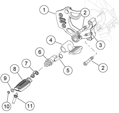
Figure 2-235. Rider foot control, right side: XR 1200X: 1. Master cylinder/footrest bracket; 2. Fastener; 3. Footrest clevis bolt; 4. Brake pedal; 5. Clevis pin; 6. Footrest clevis; 7. Spring; 8. Footrest; 9. Washer; 10. Retaining ring; 11. Wear peg
4. Remove clevis pin (5), spring (7), and footrest (8).
5. Remove bolt (3), footrest clevis (6), and brake pedal (4).
6. If necessary, remove bracket (1). The master cylinder must be disconnected from the bracket or brake line disconnected prior to removing the two fasteners (2). See 2.12 REAR BRAKE MASTER CYLINDER: XR 1200X.
Installation
1. If removed, install master cylinder/footrest bracket. See 2.12 REAR BRAKE MASTER CYLINDER: XR 1200X.
2. See Figure 2-235. Install brake pedal on footrest clevis and install footrest clevis. Tighten bolt (3) to 13-17 ft·lbs (17.6-23.0 Nm).
3. Install footrest (8) and spring (7) on clevis and secure with clevis pin (5). Install washer (9) and new retaining ring (10).
4. If removed, install wear peg and tighten to 72-108 in·lbs (8.1-12.2 Nm).
5. Connect brake pedal to master cylinder. See 2.12 REAR BRAKE MASTER CYLINDER: XR 1200X.
Left footrest and shift lever assembly
| FASTENER | TORQUE VALUE | |
| Footrest bracket fastener: XR 1200X | 45-50 ft·lbs | 61-68 Nm |
| Footrest clevis fastener: XR 1200X | 13-17 ft·lbs | 17.6-23.0 Nm |
| Shifter peg screw | 96-144 in·lbs | 10.9-16.3 Nm |
| Footrest wear peg | 72-108 in·lbs | 8.1-12.2 Nm |
| Shift linkage fastener | 120-180 in·lbs | 13.6-20.3 Nm |
Removal
1. See Figure 2-236. Remove fasteners (11) and remove linkage (12).
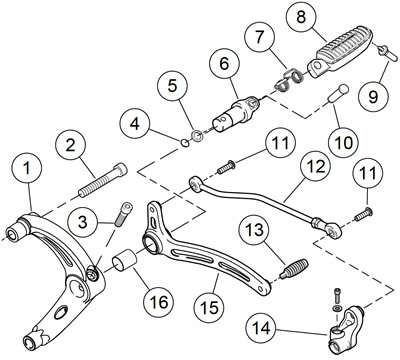
Figure 2-236. Rider foot control, left side: XR 1200X: 1. Bracket; 2. Fastener (2); 3. Footrest clevis bolt; 4. Retaining ring; 5. Washer; 6. Footrest clevis; 7. Spring; 8. Footrest; 9. Wear peg; 10. Clevis pin; 11. Fastener (2); 12. Shift linkage; 13. Shifter peg; 14. Transmission shift lever; 15. Foot shift lever; 16. Bushing
2. If necessary, remove wear peg (9).
3. Remove retaining ring (4) and washer (5). Discard retaining ring.
4. Remove clevis pin (10), spring (7), and footrest (8).
5. Remove bolt (3), footrest clevis (6), and foot shift lever (15).
6. Remove shifter peg (13).
7. If necessary, remove fasteners (2) and bracket (1).
Installation
1. See Figure 2-236. If removed, install bracket (1). Tighten fasteners (2) to 45-50 ft·lbs (61-68 Nm).
2. Install foot shift lever on footrest clevis. Install footrest clevis and bolt (3). Tighten to 13-17 ft·lbs (17.6-23.0 Nm).
3. Install footrest (8) and spring (7) on clevis. Secure with clevis pin (10). Install washer (5) and new retaining ring (4).
4. Install shifter peg (13). Tighten to 96-144 in·lbs (10.9-16.3 Nm).
5. If removed, install wear peg. Tighten to 72-108 in·lbs (8.112.2 Nm).
6. Connect linkage (12) between foot shift lever (15) and transmission shift lever (14) using fasteners (11). Tighten to 120-180 in·lbs (13.6-20.3 Nm).
7. Check shift linkage adjustment. Adjust as necessary.
Adjusting shift lever
| FASTENER | TORQUE VALUE | |
| Shift rod screw | 120-180 in·lbs | 13.6-20.4 Nm |
| Shift rod jamnuts | 84-132 in·lbs | 9.5-14.9 Nm |
The foot shift linkage is set at the factory and normally should need no adjustment. However, the shift linkage can be adjusted for rider preference.
See Figure 2-237. Adjust shifter rod assembly (4) length until shifter lever (5) is at approximately 20 degrees from horizontal as shown in the figure.
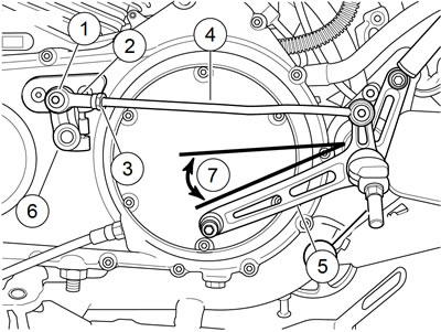
Figure 2-237. Adjusting shift pedal: XR 1200X: 1. Screw; 2. Ball joint; 3. Jamnut; 4. Shifter rod; 5. Shifter lever assembly; 6. Shifter arm; 7. 20 degrees
1. Loosen jamnut (3) on front end of shifter rod.
2. Remove screw (1) securing ball joint (2) to shifter arm (6).
3. Turn ball joint in one direction or the other to adjust rod length as necessary. Temporarily attach ball joint to shifter arm and check angle.
4. When angle of shift lever assembly is at 20 degrees, install screw (1). Tighten to 120-180 in·lbs (13.6-20.4 Nm).
5. Holding ball joint with a wrench on the flats, tighten the jamnuts to 84-132 in·lbs (9.5-14.9 Nm).