Purging and disconnecting fuel supply hose
Warning! Stop the engine when refueling or servicing the fuel system. Do not smoke or allow open flame or sparks near gasoline. Gasoline is extremely flammable and highly explosive, which could result in death or serious injury.
Warning! When servicing the fuel system, do not smoke or allow open flame or sparks in the vicinity. Gasoline is extremely flammable and highly explosive, which could result in death or serious injury.
Warning! To prevent spray of fuel, purge system of high-pressure fuel before supply line is disconnected. Gasoline is extremely flammable and highly explosive, which could result in death or serious injury.
Warning! Do not use solvents or other products that contain chlorine on plastic fuel system components. Chlorine can degrade plastic fuel system components, which can cause a loss of fuel system pressure or engine stalling and could result in death or serious injury.
1. Purge the fuel supply line of high pressure gasoline.
- a. See Figure 4-12. Unplug fuel pump connector [141].
- b. Start engine and allow vehicle to run.
- c. When engine stalls, operate starter for 3 seconds to remove any remaining fuel from fuel hose.
- d. Shut off ignition.

Figure 4-12. Fuel pump connector location
Warning! Gasoline can drain from quick-connect fitting when removing fuel line. Gasoline is extremely flammable and highly explosive, which could result in death or serious injury. Wipe up spilled fuel immediately and dispose of rags in a suitable manner.
2. See Figure 4-13. Push up on release sleeve (1) on fuel pump quick-connect fitting and pull down on fuel supply hose fitting (2) to disconnect fuel supply hose (3). Immediately clean up any fuel spills.
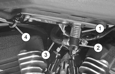
Figure 4-13. Fuel tank quick-connect fitting: 1. Release sleeve (quick-connect fitting); 2. Fuel supply hose fitting; 3. Fuel supply hose; 4. Throttle cable retainer
Removing fuel tank
1. Purge the fuel supply line of high pressure gasoline. Disconnect fuel line from fuel tank. See 6.3 FUSES AND RELAYS, Main Fuse.
Warning! To prevent accidental vehicle start-up, which could cause death or serious injury, remove main fuse before proceeding.
2. Remove main fuse.
Notes:
- If the fuel tank is being removed only to gain access to items otherwise hidden, it is not necessary to drain the fuel from the tank. If the fuel tank is to be disassembled or repaired, drain the fuel tank.
- Drain fuel into an approved container.
3. Drain fuel tank:
- a. Obtain a suitable fuel transfer pump with a long, flexible nozzle.
- b. Position vehicle upright. Remove fuel tank filler cap.
- c. Insert fuel transfer pump nozzle into fuel tank filler spout. Aim nozzle toward right side of fuel tank to avoid contacting and damaging fuel pump assembly.
- d. Direct the pump output into an approved container.
- e. Pump fuel until fuel tank is empty.
- f. Replace fuel tank filler cap.
- g. Immediately wipe up any spilled fuel.
4. See Figure 4-13. Remove retainer (4) securing throttle cables to plate on bottom of fuel tank.
Note. See Figure 4-14. Short screws (2) secure trim ring to fuel tank cover only. It is not necessary to remove these screws unless either trim ring or fuel tank cover is being replaced.
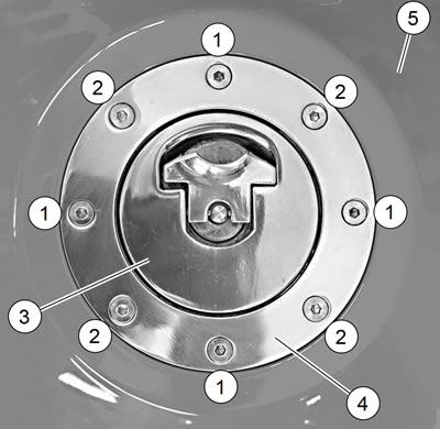
Figure 4-14. Fuel cap and trim ring: 1. Screw, long (4); 2. Screw, short (4); 3. Fuel cap; 4. Trim ring; 5. Fuel tank cover
5. See Figure 4-14. Remove four long screws (1) that secure trim ring (4) and fuel tank cover (5) to fuel tank.
6. Carefully lift fuel tank cover off fuel tank. Slide cover forward slightly as it is lifted to clear sides of fuel tank.
7. See Figure 4-15. Remove vent hose (3) from fuel tank vent fitting (4). With a gentle twisting motion, pull ground wire connector [210] (5) straight up off pin on fuel tank clamp ring (6).
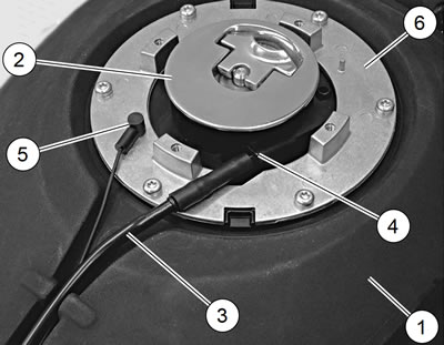
Figure 4-15. Fuel tank vent hose and ground wire: 1. Fuel tank; 2. Fuel cap; 3. Vent hose; 4. Vent fitting; 5. Ground wire connector [210]; 6. Clamp ring
8. Remove vent hose and ground wire from trough in center of fuel tank. Pull vent hose and ground wire back out of the way.
9. See Figure 4-16. Remove two screws and washers (3) securing air box to bottom of fuel tank.

Figure 4-16. Fuel tank and air box mounting fasteners: 1. Fuel tank; 2. Air box; 3. Screw w/washer (2); 4. Screw w/washer; 5. Rubber grommet; 6. Screw w/washers and locknut
10. Remove screw with washer (4) from rear of fuel tank. Remove protective plastic cap (not shown) from threaded end of screw (6). Remove screw, washers and locknut from the front of the fuel tank.
11. See Figure 4-13. Remove throttle cable retainer (4) from fuel tank.
12. Lift fuel tank off motorcycle.
Note. See Figure 4-19. Metal bushings (4) inside the grommets (3) may fall when fuel tank is lifted off vehicle. Make sure they do not fall out and become lost.
13. Remove fuel pump assembly from fuel tank. See 4.16 FUEL PUMP.
Disassemble fuel tank
Warning! When servicing the fuel system, do not smoke or allow open flame or sparks in the vicinity. Gasoline is extremely flammable and highly explosive, which could result in death or serious injury.
1. See Figure 4-17. Remove filler cap (1) with O-ring (2).
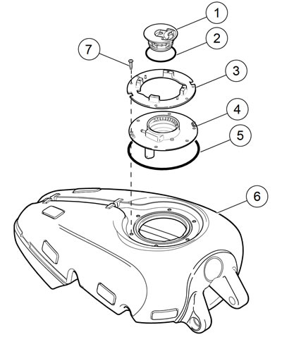
Figure 4-17. Fuel tank assembly: 1. Filler cap; 2. O-ring; 3. Clamp ring; 4. Top ring; 5. O-ring; 6. Fuel tank; 7. Screw (6)
2. Remove screws (7) and clamp ring (3).
3. Remove top ring (4).
4. Remove O-ring (5).
Cleaning and inspection
Warning! When servicing the fuel system, do not smoke or allow open flame or sparks in the vicinity. Gasoline is extremely flammable and highly explosive, which could result in death or serious injury.
1. Clean fuel tank interior with commercial cleaning solvent or a soap and water solution. Shake fuel tank to agitate cleaning agent.
2. Thoroughly flush fuel tank after cleaning. Allow fuel tank to air dry.
3. Carefully inspect fuel hose and vent hose for damage, cuts, cracks, holes, wearorgeneral deterioration. Replace as necessary.
4. Inspect the fuel tank for leaks or other damage. Replace the tank if necessary.
Assemble fuel tank
| FASTENER | TORQUE VALUE | |
| Filler housing screws | 40-45 in·lbs | 4.5-5.1 Nm |
Warning! When servicing the fuel system, do not smoke or allow open flame or sparks in the vicinity. Gasoline is extremely flammable and highly explosive, which could result in death or serious injury.
1. See Figure 4-17. Install new O-ring (5) on the fuel tank (6). Verify that it is seated properly.
2. Install top ring and clamp ring with screws (7).
3. See Figure 4-18. Tighten screws in the sequence shown to 40-45 in·lbs (4.5-5.1 Nm).
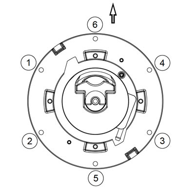
Figure 4-18. Filler housing torque sequence
4. See Figure 4-17. Install filler cap (1) with a new O-ring (2).
Installing fuel tank
| FASTENER | TORQUE VALUE | |
| Air box to bracket fasteners: XR 1200X | 36-60 in·lbs | 4.1-6.7 Nm |
| Fuel tank fastener: XR 1200X | 15-20 ft·lbs | 20.3-27.1 Nm |
| Fuel tank fastener: XR 1200X | 15-20 ft·lbs | 20.3-27.1 Nm |
| Fuel tank cover screw: XR 1200X | 24-30 in·lbs | 2.7-3.4 Nm |
Note. Be sure that wiring harnesses do not get pinched between fuel tank and frame during tank installation.
1. Install fuel pump into fuel tank using new gasket. See 4.16 FUEL PUMP.
2. See Figure 4-19. Install rubber grommets (3) in both front mounting holes of fuel tank. Insert metal bushings (4) into rubber grommets, oriented as shown. Verify that the clip nut (5) is installed on frame bracket.

Figure 4-19. Fuel tank mounting: 1. Rear screw; 2. Washer (3); 3. Rubber grommet (6); 4. Metal bushing (3); 5. Clip nut; 6. Front screw; 7. Locknut; 8. Cap
Notes:
- Verify that the ignition coil bracket is positioned between the tank mount and the frame.
- Verify that the air box mounting brackets are mated.
3. Position fuel tank on motorcycle.
4. Insert screw (6) with washer (2) through fuel tank front mounting brackets and vehicle frame. Install remaining washer and locknut (7) on other end of screw. Do not tighten at this time.
5. Secure pump harness to main harness retainer located under fuel tank.
6. Install rubber grommets (3) in rear mounting hole of fuel tank.
Note. Verify that the air box grommet is securely installed on induction module and air box opening. An improperly seated grommet could lead to accelerated engine wear. See 4.3 AIR CLEANER ASSEMBLY XR 1200X.
7. Secure air box to brackets on bottom of fuel tank. Tighten to 36-60 in·lbs (4.1-6.7 Nm).
8. Mount the fuel tank.
- a. Locate the metal bushing (4) inside the rear lower rubber grommet (3) of fuel tank.
- b. Install screw (1), washer (2) and upper grommet (3).
- c. Thread into clip nut (5). Tighten to 15-20 ft·lbs (20.327.1 Nm).
- d. Tighten front screw (6) and locknut (7) to 15-20 ft·lbs (20.3-27.1 Nm).
9. See Figure 4-13. Secure throttle cables to bottom of fuel tank using a new loop retainer.
10. See Figure 4-15. Connect vent hose (3) and ground wire (5) as shown. Route ground wire and vent hose in trough in top of tank.
11. See Figure 4-14. Install fuel tank cover and secure with four screws (1). Tighten screws to 24-30 in·lbs (2.7-3.4 Nm).
12. Connect fuel pump connector [141].
13. Connect fuel supply fitting. See 4.5 FUEL TANK: XR 1200X, Connecting Fuel Hose and Filling Fuel Tank.
Connecting fuel hose and filling fuel tank
Warning! To prevent spray of fuel, be sure quick-connect fittings are properly mated. Gasoline is extremely flammable and highly explosive, which could result in death or serious injury.
1. See Figure 4-13. Connect the fuel hose fitting:
- a. Push up on release sleeve (1).
- b. Push fuel hose fitting (2) into fuel pump module fuel pump quick-connect fitting.
- c. Pull down on release sleeve to lock quick-connect fitting.
- d. Tug on fuel hose fitting to make sure it is securely locked in place.
Warning! Use care when refueling. Pressurized air in fuel tank can force gasoline to escape through filler tube. Gasoline is extremely flammable and highly explosive, which could result in death or serious injury.
Warning! Avoid spills. Slowly remove filler cap. Do not fill above bottom of filler neck insert, leaving air space for fuel expansion. Secure filler cap after refueling. Gasoline is extremely flammable and highly explosive, which could result in death or serious injury.
2. Fill fuel tank and carefully inspect for leaks around fuel pump module.
3. Install main fuse.
4. Turn ignition switch ON and verify fuel pump is activated. Carefully inspect for leaks at quick-connect fitting and induction module. Turn ignition switch OFF.
5. Install left side cover.
