Then follow all steps listed in the following sections, including inspection and repair procedures: See 3.14 CYLINDER HEAD and 3.15 CYLINDER AND PISTON.
Note. Clean engine before disassembly. Abrasive particles can damage machined surfaces or plug oil passageways. Remove all dirt and particles before disassembly to prevent component damage.
Stripping motorcycle for top end repair
Warning! When servicing the fuel system, do not smoke or allow open flame or sparks in the vicinity. Gasoline is extremely flammable and highly explosive, which could result in death or serious injury.
1. Purge the fuel supply hose of high pressure gasoline. Disconnect fuel supply hose from fuel pump module. See 4.4 FUEL TANK: XL MODELS or 4.5 FUEL TANK: XR 1200X.
2. Remove seat.
Warning! To prevent accidental vehicle start-up, which could cause death or serious injury, remove main fuse before proceeding.
3. Remove main fuse.
4. Unplug O2 sensor connectors [137], [138] and remove exhaust pipes and mufflers. See 4.13 EXHAUST SYSTEM: XL MODELS or 4.14 EXHAUST SYSTEM: XR 1200X.
5. Disconnect spark plug cables from spark plugs.
6. Drain and remove fuel tank. See 4.4 FUEL TANK: XL MODELS or 4.5 FUEL TANK: XR 1200X.
7. Remove horn.
- a. Front Mount: See 6.32 HORN, Replacement: Front Mount.
- b. Side Mount: See 6.32 HORN, Replacement: Side Mount.
8. Remove air cleaner assembly:
- a. XL Models except XL 1200V: Remove cover, air filter and air cleaner backing plate. See 4.3 AIR CLEANER ASSEMBLY, XL Models except XL 1200V.
- b. XL 1200V: Remove cover, air filter and air cleaner backing plate. See 4.3 AIR CLEANER ASSEMBLY, XL 1200V.
- c. CA Models: Remove EVAP purge hose from induction module. See 4.20 EVAPORATIVE EMISSIONS CONTROL.
9. Remove induction module. See 4.8 INDUCTION MODULE: XL MODELS or 4.9 INDUCTION MODULE: XR 1200X.
10. Secure induction module assembly and throttle cables out of the way.
11. See Figure 3-39. Remove upper front stabilizer link and frame bracket:
- a. Remove screw (4) securing stabilizer link (2) to engine bracket (1).
- b. Remove screws (5) and washers (8). Remove horn bracket (9) (models with front mounted horn) and frame bracket (3) with stabilizer link.
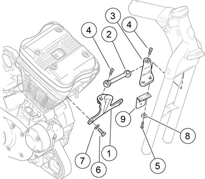
Figure 3-39. Upper front stabilizer link assembly: 1. Engine bracket; 2. Upper stabilizer link; 3. Upper frame bracket; 4. Screw; 5. Screw (2); 6. Screw (2); 7. Lock washer (2); 8. Washer (2); 9. Horn bracket
Cylinder heads
Disassembling rocker covers
Notice: Prevent engine damage. Washers and fasteners used in the engine are hardened parts. Do not use unhardened parts.
1. Remove spark plugs.
2. See Figure 3-42. Remove four screws with captive washers (1) and sealing washers (2). Discard sealing washers.
3. Remove outer rocker cover (3) or (20).
4. Remove and discard gaskets (4, 5).
5. Rotate crankshaft until both valves are closed on head being removed.
6. See Figure 3-40. Remove hardware securing inner rocker cover to cylinder head in the following order.
- a. Remove two screws and washers (1).
- b. Remove three bolts and washers (2).
- c. Loosen four rocker arm bolts (3) in 1/4-1/2 turn increments using a cross pattern. This relieves valve spring pressure evenly on inner rocker cover.
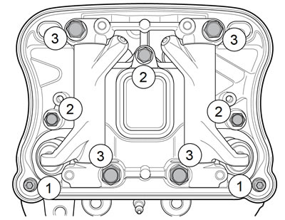
Figure 3-40. Inner rocker cover fasteners (typical): 1. Screws and washers; 2. Bolts and washers; 3. Rocker arm bolts
7. See Figure 3-42. Remove inner rocker cover (8) or (24). Remove and discard gasket (16).
8. Remove breather assembly:
- a. XL Models: Remove screw (6), breather assembly (7) and breather seal (17). Discard seal.
- b. XR 1200X: Push breather assembly (23) and O-ring (22) out from the under side.
Note. Mark rocker arm shafts for reassembly in their original positions. Install valve train components in their original positions or increased engine wear may result.
9. See Figure 3-41. Remove rocker arm shafts by tapping them out using a hammer and a soft metal punch.

Figure 3-41. Removing rocker arm shafts (typical): 1. Retaining notch; 2. Position of rocker arm retaining bolts
10. See Figure 3-42. Remove rocker arms (11, 12). Mark the rocker arms for reassembly in their original locations.
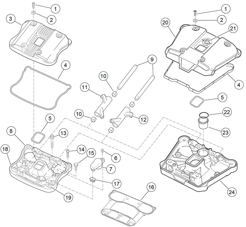
Figure 3-42. Rocker cover assembly: 1. Screw w/captive washer (4); 2. Sealing washer (4); 3. Outer rocker cover: XL Models; 4. Gasket; 5. Gasket; 6. Screw; 7. Breather assembly: XL Models; 8. Inner rocker cover: XL Models; 9. Rocker arm shaft (2); 10. Rocker arm bushing (4); 11. Rocker arm; 12. Rocker arm; 13. Bolt (4); 14. Screw (2); 15. Bolt (3); 16. Gasket; 17. Breather seal: XL Models; 18. Breather location: Front Cylinder: XL Models; 19. Breather location: Rear Cylinder: XL Models; 20. Outer rocker cover: XR 1200X; 21. Breather hose fitting hole: XR 1200X; 22. O-ring: XR 1200X; 23. Breather filter and valve assembly: XR 1200X; 24. Inner rocker cover: XR 1200X
Removing cylinder head
Note. See Figure 3-43 or Figure 3-44. Follow sequence of incremental removal as described below to prevent component damage.
1. XR 1200X: Remove precision cooling lines. See 3.12 PRECISION COOLING SYSTEM: XR 1200X, Cylinder Head Oil Return Lines.
2. See Figure 3-43 and Figure 3-44. Loosen each head bolt 1/8-turn following the sequence shown.
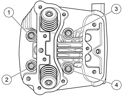
Figure 3-43. Front cylinder headbolt torque sequence: 1. Short bolt; 2. Short bolt; 3. Long bolt; 4. Long bolt
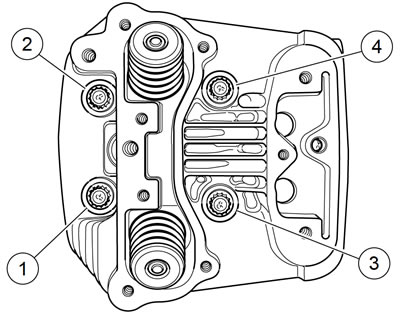
Figure 3-44. Rear cylinder headbolt torque sequence: 1. Short bolt; 2. Short bolt; 3. Long bolt; 4. Long bolt
3. Continue loosening in 1/8-turn increments until screws are loose. Remove head screws.
4. Remove cylinder head and head gasket. Discard head gasket.
Disassembling pushrods and covers
1. See Figure 3-45. Remove pushrod covers (2), O-rings (1, 3) and push rods (4). Mark the location and orientation (top and bottom) of each pushrod. Discard O-rings.

Figure 3-45. Middle valve train components: 1. O-ring (4); 2. Pushrod cover (4); 3. O-ring (4); 4. Pushrod (4); 5. Screw (8); 6. Washer (8); 7. Tappet cover (2); 8. Gasket (2); 9. Screw (2); 10. Anti-rotation device (2); 11. Tappet (4); 12. Right crankcase
2. Remove socket screws (5) and washers (6). Remove tappet cover (7) and gasket (8). Discard gasket.
Cylinder and piston
| PART NUMBER | TOOL NAME |
| HD-34623-C | PISTON PIN LOCKRING REMOVER/INSTALLER |
| HD-42320-A | PISTON PIN REMOVER |
| HD-42322 | PISTON SUPPORT PLATE |
1. Clean engine before disassembly.
2. See Figure 3-46. Rotate crankshaft until piston (6) of cylinder being removed is at bottom of its stroke.
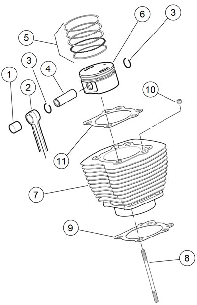
Figure 3-46. Cylinder and piston: 1. Piston pin bushing; 2. Connecting rod; 3. Lock ring (2); 4. Piston pin; 5. Piston ring set; 6. Piston; 7. Cylinder; 8. Cylinder stud (4); 9. Cylinder base gasket; 10. Dowel (2); 11. Head gasket
3. Carefully raise cylinder just enough to permit placing clean towel under piston to prevent any foreign matter from falling into crankcase.
Note. If cylinder does not come loose, tap lightly with rawhide or plastic hammer perpendicular to cylinder fins. Never try to pry cylinder up.
4. Carefully lift cylinder over piston and cylinder studs (8). Do not allow piston to fall against cylinder studs.
Note. To avoid damage to piston assembly and/or cylinder studs, do not allow piston to fall against studs.
5. Discard cylinder base gasket (9).
Note. With cylinder removed, be careful not to bend the cylinder studs. The slightest bend could cause a stress riser and could lead to stud failure.
6. Install a 6.0 in (150 mm) length of 1/2 in (12.7 mm) ID plastic or rubber hose over each cylinder stud. This will protect the studs and the pistons.
Notice: Handle piston with extreme care. The alloy used in these pistons is very hard. Any scratches, gouges or other marks in the pistons could score the cylinder during engine operation and cause engine damage.
Warning! Wear safety glasses or goggles when removing or installing piston pin retaining rings. Piston pin retaining rings are compressed in the ring groove and can fly out when removed from the groove, which could result in serious eye injury.
7. See Figure 3-47. Remove piston pin lock ring as follows:
- a. Insert PISTON PIN LOCK RING REMOVER/INSTALLER (Part No. HD-34623-C) into piston pin bore until claw on tool is positioned in slot of piston (directly under lock ring).
- b. Squeeze handles of tool together and pull from bore. Hold a shop towel over bore during removal in the event that the lock ring should fly out. Remove lock ring from claw and discard.
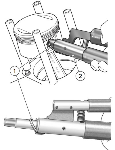
Figure 3-47. Removing piston pin lock ring: 1. Piston pin lock ring; 2. Piston pin lock ring installer
Notes:
- It is not necessary to remove both piston pin lock rings during piston removal. Leave second lock ring in piston pin bore.
- Do not reuse piston pin lock rings. Removal may weaken lock rings and they may break or dislodge if reused, resulting in engine damage.
Note. To avoid damage to piston or cylinder base studs, use PISTON SUPPORT PLATE (Part No. HD-42322) to secure piston in place while removing piston pin.
8. Remove piston pin. Since pin is a loose fit in piston, pin should easily slide out. If pin is difficult to remove, use PISTON PIN REMOVER (Part No. HD-42320-A), as follows:
- a. See Figure 3-48. Remove acorn nut and spacer (1) from rod end of tool.
- b. Slide rod end through piston pin. Install spacer and acorn nut on end of rod.
- c. Position rubber coated tips (2) of tool on flat on each side of piston pin bore.
- d. Hold tool body (3) and turn handle (4) clockwise until piston pin is pulled free of bore.

Figure 3-48. Removing piston pin with HD-42320-A piston pin remover: 1. Acorn nut and spacer; 2. Rubber coated tip (2); 3. Tool body; 4. Handle
9. Remove piston from connecting rod. Be sure to hold connecting rod shank upright to prevent it from striking crankcase.
10. Place a 3.0 in (76.2 mm) length of 1.0 in (25.4 mm) ID foam-type water pipe insulation around each connecting rod to prevent damage.
11. Mark each pin boss with either an "F" or an "R" to indicate front or rear cylinder, respectively.
12. Spread piston rings outward until they clear grooves in piston and lift off.
