Bulb replacement
1. Locate notch on edge of front or rear turn signal lens cap.
2. Insert coin in notch. Carefully twist coin until lens pops out of turn signal housing.
3. Replace bulb.
- a. Push bulb in and turn counterclockwise.
- b. Pull bulb from socket when tab on bulb clears opening on socket.
- c. Push new light bulb in and turn clockwise to lock in place.
4. Snap lens back into turn signal housing with the notch facing down.
Note. If after replacing a bulb, the turn signal or running lamp will not light, check the wiring, the ground at the socket and/or the switch.
Lamp replacement
General
1. Remove maxi-fuse. See 8.5 Maxi-fuse.
2. Change turn signal following steps under Front Turn Signals or Rear Turn Signals in this section.
3. Replace maxi-fuse. See 8.5 Maxi-fuse.
Front turn signals
Note. Before removing turn signal wires, carefully note routing. In particular, pay close attention to the locations of cable straps which must be replaced.
1. See 8.15 Instrument cluster. Remove front handlebar cover and instrument cluster.
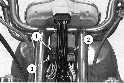
2. See Figure 8-26. Clip cable strap around handlebar control connectors and electrical bracket.

Figure 8-26. Handlebar control connectors: 1. Right handlebar controls connector [22]; 2. Left handlebar controls connector [24]; 3. Electrical bracket
3. Pull electrical bracket away from handlebar uprights.
4. Front turn signal connector socket [31 A] is attached to back side of electrical bracket. Disconnect front turn signal connector [31B] from socket.
5. Note locations of turn signal wires in connector. Remove appropriate turn signal wire terminals from connector. See the VRSCA Electrical Diagnostic Manual for more information. Remove turn signal wire harness from handlebar clips.
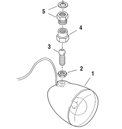
6. See Figure 8-27. Hold retainer (5) and loosen ball stud clamp (4) to remove turn signal (1).

Figure 8-27. Front turn signal mounting: 1. Turn signal; 2. Jam nut; 3. Ball stud; 4. Ball stud clamp; 5. Retainer and washer
7. Lay old turn signal assembly next to new one and cut new wires to length. Trim sheath back approximately 63.5 mm (2.5 in) from ends of wires. Crimp new terminals onto wires. See the VRSCA Electrical Diagnostic Manual for more information.
8. Install new turn signal lamp housing and route wire harness through handlebar clips. Insert terminals into turn signal connector and mate connector to socket.
9. Install cable strap around electrical bracket, handlebar control connectors and turn signal connector.
10. Press electrical bracket back in place between handlebar uprights.
11. See 8.15 Instrument cluster. Install instrument cluster and handlebar covers.
Rear turn signals
Note. Before removing turn signal wires, carefully note routing and location of each wire terminal in connector.
1. See 8.12 Tail lamp. Remove tail lamp housing assembly from rear fender. Locate appropriate rear turn signal harness and connector inside tail lamp housing recess in rear fender.
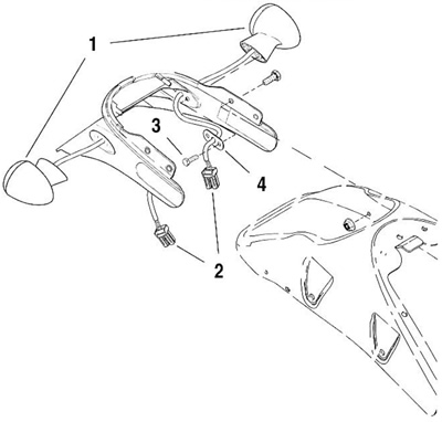
2. See Figure 8-28. Drawing shows rear lighting module assembly removed from rear fender for clarity. Note locations of turn signal wires in connector (2). Remove turn signal wire terminals from connector. See the VRSCA Electrical Diagnostic Manual for more information.

Figure 8-28. Rear turn signal mounting: 1. Turn signal assembly(2); 2. Turn signal connector (2); 3. Fastener (4); 4. Support plate (2)
3. Remove fasteners (3) and support plate (4). Remove turn signal housing (1) from vehicle. Carefully pull turn signal wiring harness through holes in fender.
4. Install new turn signal housing and support plate, routing wiring harness back through holes in fender. Bring wire ends into tail lamp housing recess in rear fender.
5. Insert terminals into turn signal connector and mate connector to socket.
6. See 8.12 Tail lamp and install tail lamp housing assembly into rear fender.
