
Removal
1. Allow cooling system to cool.
2. Remove right side cover and maxi-fuse. See 8.5 Maxi-fuse.
Warning! To protect against shock and accident start-up of vehicle, disconnect the negative battery cable before proceeding. Inadequate safety precautions could result in death or serious injury.
3. Remove the negative battery cable.
Warning! Do not remove the filler cap when the engine is hot. The cooling system is under pressure and hot coolant and steam may escape causing severe burns. Allow engine to cool before servicing the cooling system.
4. Open seat and remove pressure cap.
5. Remove left side radiator cover. Remove radiator plug and drain engine coolant into suitable container.
6. Remove air filter top, air filter, breather hose, velocity stacks and air filter bottom. See 1.4 Airbox and air filter.
7. See Figure 6-16. Loosen pipe clamp (4). Loosen and remove fastener (7) holding p-clamp (8) to engine.
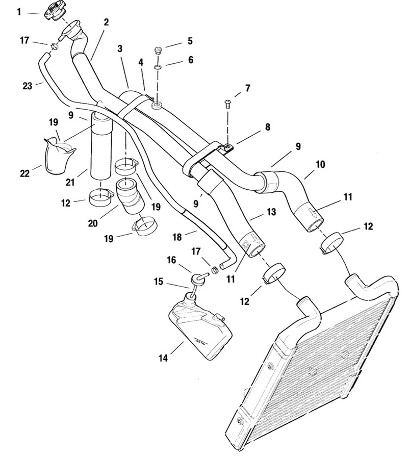
Figure 6-16. Coolant pipes and hoses: 1. Pressure cap; 2. Coolant inlet pipe; 3. Coolant outlet pipe; 4. Pipe clamp @ 6.5 Nm (57 in-lbs); 5. Air bleed plug @ 9-11 Nm (80-97 in-lbs); 6. Seal; 7. Fastener; 8. P-clamp @ 6-10 Nm (53-88 in-lbs'; 9. Shrink clamp; 10. Hose - engine coolant outlet pipe io radiator; 11. Embossed arrow - top and front; 12. Clamp - bright @ 3-4 Nm (27-35 in-lbs); 13. Hose - coolant inlet pipe to radiator; 14. Overflow bottle; 15. Hose; 16. Cap; 17. Clamp - overflow hose; 18. Sleeve hose; 19. Clamp - black @ 3-4 Nm (27-35 in-lbs); 20. Hose; 21. Hose; 22. Hose cover; 23. Overflow hose
8. Squeeze clamp (17) and pull off end of overflow hose (23) at overflow bottle (14). Pull drain hose to radiator/oil cooler off overflow bottle. Remove overflow bottle (14).
9. Loosen clamps (12, 19) on bottom of hoses to water pump and thermostat.
10. Use a long thin screwdriver (Snap-on Part No. SDD1410) to loosen clamps (12) and pull hoses (10, 13) off radiator.
11. Remove engine coolant pipes (2, 3) with hoses (10, 13, 20, 21).
Disassembly
1. See Figure 6-16. Cut shrink clamps (9) from the coolant inlet and the coolant outlet pipes (2, 3) and hoses (10, 13, 21).
Note. To remove shrink clamps without cutting, use a soldering iron and, carefully, melt a slice through the band without damaging the hose.
2. Loosen overflow hose clamp (17) and remove overflow hose (23) from filler neck.
3. Remove hose cover (22) and loosen upper clamp (19) from the water pump to coolant inlet pipe hose.
4. Clean hose mounting stems on the engine coolant inlet pipe (2) and the engine coolant outlet pipe (3) with a wire brush.
5. Inspect all components and replace as required.
Assembly
| PART NO. | SPECIALTY TOOL |
| HD-25070 | Robinair heat gun |
1. See Figure 6-16. If removed, thread the air bleed plug (5) with new seal (6) into the coolant outlet pipe (3).
2. Remove new shrink clamp (9) from packaging brace by squeezing band to collapse, then fold in half and remove from cardboard. Slide shrink clamps over hoses.
3. Orient radiator hoses with embossed arrow (11) on top and towards front. Push hose over fitting beads on coolant inlet and coolant outlet pipes (2, 3).
4. Orient shrink clamps (9) so print on the clamp is visible after shrinking. Slide clamp over end of hose to overlap the bulge formed by fitting bead of coolant pipe.
Caution! Do NOT use open flame to shrink clamp. Using an open flame could result in uncontrolled melting of clamp.
5. Using an ROBINAIR HEAT GUN (Part No. HD-25070) or similar tool, apply heat to shrink clamps (9). Move heat tool around clamp continuously to prevent burning.
Note. Heated area must cover at least 1/3 of clamp surface. If heating shrink clamp while hose and pipe are still mounted in motorcycle, take care not to damage surrounding components.
6. Heat until print turns grey and them remove heat.
Note. Check seal by trying to rotate hose on fitting by hand. Hose and clamp should NOT turn when using reasonable torque.
7. Repeat for each shrink clamp required.
Installation
1. See Figure 6-16. With upper black clamp (19) on hose (20) and lower black clamp (19) loose, install coolant outlet pipe (3).
2. With embossed arrow (11) pointing towards front and on top, push hose (10) over neck bead of radiator inlet neck. Push hose (20) onto outlet neck of thermostat housing.
Note. A lubricant, tire soap or detergent and water, can be used to lubricate the hose to aid in pushing hose over neck beads.
3. With hose cover (22), clamp (19), and bright clamp (12) loose on hose, install coolant inlet pipe (2).
4. With embossed arrow (11) pointing towards front and on top, push hose (13) over neck bead of radiator outlet and push hose (21) over water pump inlet neck.
5. Use a long thin screwdriver (Snap-on Part No. SDD1410) to tighten worm drive clamps (12, 19) to 3-4 Nm (27-35 in-lbs).
6. Install p-clamp (8) and pipe clamp (4) over both pipes. Tighten pipe clamp (4) to 6.5 Nm (57 in-lbs) and tighten p-clamp to 6-10 Nm (53-88 in-lbs).
7. Install, through right side cover opening, overflow bottle (14) with hose (15), and cap (16). L-shaped catch on bottom of bottle fits to slot in battery bracket. Push on drain hose to radiator/oil cooler assembly.
8. Install and clamp overflow hose (23) to filler neck and overflow bottle cap (16).
9. Pressure test to 103 kPa (15 psi).
10. Install air filter bottom, velocity stacks, о-rings, and breather hose. See 1.4 Airbox and air filter.
11. Loosen air bleed plug. Fill with GENUINE HARLEY-DAVIDSON EXTENDED LIFE ANTIFREEZE & COOLANT through filler neck.
12. Tighten air bleed plug to 9-11 Nm (80-97 in-lbs). and replace pressure cap.
13. Replace the negative battery cable. Tighten to 6.8-10.8 Nm (60-96 in-lbs).
14. Install air filter, air filter top and airbox cover.
15. Install right side cover and maxi-fuse.
16. Rinse motorcycle with water to remove any spilled col-lant.
17. After running engine, check coolant level in overflow bottle with coolant cold and motorcycle on jiffy stand. If level is below COLD FULL line, remove cap from overflow bottle and add antifreeze until fluid level reaches COLD FULL line.
18. Continue to run engine, check level, and add antifreeze until fluid level remains at COLD FULL line with the motorcycle on the jiffy stand.