| PART NO. | SPECIALTY TOOL |
| HD-45314 | Crankshaft rotating wrench |
| HD-45340 | Gasket alignment tool |
1. See Figure 1-66. Using CRANKSHAFT ROTATING WRENCH (HD-45314), rotate the engine counter-clockwise (direction of operation) to position front cylinder cam lobes at 10 o’clock and 2 o’clock.

Figure 1-66. Front cylinder 10 and 2 o’clock cam lobe position
2. See Figure 1-67. Clean oil from cam drive gear and chain link. Make a reference mark on chain and cam drive gear, both intake and exhaust, as shown.
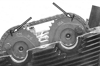
Figure 1-67. Reference mark cam gear and chain link
Note. Copper colored links are for initial assembly of complete cam drive system.
3. See Figure 1-68. Remove secondary cam chain tensioner.
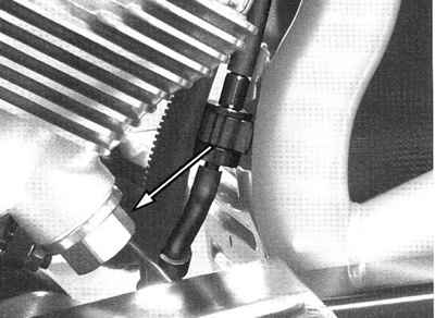
Figure 1-68. Secondary cam chain tensioner
Caution! NEVER rotate engine with secondary cam chain tensioner removed. Engine damage and/or loss of correct timing will occur.
Caution! Do not remove cam drive gear bolts. It is not necessary for the lash adjustment.
4. See Figure 1-69. Remove cam journal fasteners and caps from the cam needing adjustment.
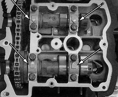
Figure 1-69. Cam journal caps
Note. Remove and adjust only one camshaft at a time.
5. See Figure 1-70. Carefully move cam and drive gear aside. Keep cam drive gear and chain engaged.
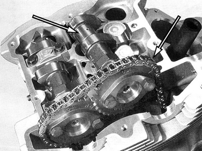
Figure 1-70. Move cam aside with chain engaged
Note. Handle chain and cam assembly carefully so as not to remove reference marks.
6. Carefully remove tappet. Oil film will usually cause shim to adhere to the under side of the tappet. Take care that shim does not dislodge and fall into engine. To remove tappet, use of a strong magnet is suggested. This will keep shim and tappet together during removal.
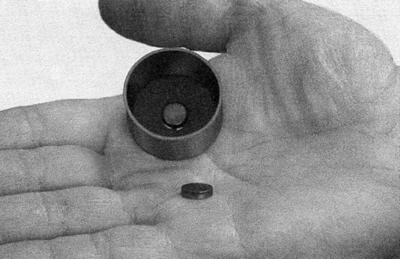
Figure 1-71. Tappet and shim
7. Use a micrometer to measure the thickness of the removed shim. Record measurement in the "Installed Shim Measurement" column on valve lash calculation worksheet. See D.2 Valve lash calculation worksheet 1.

Figure 1-72. Cam, tappet, shim relationship: 1. Camshaft; 2. Tappet; 3. Shim
Caution! Do not use shim stock to adjust valve lash. Shim stock may dislodge and cause severe engine damage.
8. Calculate and record on the valve lash calculation worksheet the "New Shim Lower Limit" and the "New Shim Upper Limit."
9. Calculate and record "Desired Shim Size."
10. Select and record the "Closest Shim Size" replacement shim. See Table D-1. Case 1 valve tappet shims and Table D-2. Case 2 valve tappet shims.
11. Always confirm new shim thickness with micrometer. Record for reference.
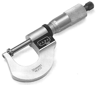
Figure 1-73. Measure shim
12. See Figure 1-74. Position new shim in spring retainer pocket. Use a magnet to position the shim and carefully push into place with finger.

Figure 1-74. Position shim
13. Replace tappet.
14. If the initial lash measurement of the remaining valve exceeds the upper or lower valve lash limits, preform the lash adjustment on the remaining valve.
15. See Figure 1-67. Install cam in alignment with new reference marks on drive chain and cam drive gear. Note new reference marks from step 2.
16. See Figure 1-75. Cam journal caps are numbered. Install cam journal caps with corresponding number on head, arrow pointing to center of head. Lubricate cam journal and journal cap with oil before placing in position.
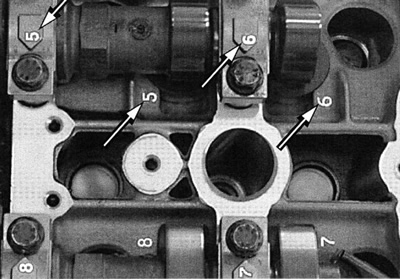
Figure 1-75. Cam journal cap reference numbers
17. Tighten cam bearing caps to 10 Nm (89 in-lbs).
18. Review the valve lash calculation worksheet and make adjustments to the valves activated by the opposite cam if necessary.
Caution! NEVER rotate engine with secondary cam chain tensioner removed. Engine damage and/or loss of correct timing will occur.
19. When second cam has been set aside, the valve lash adjusted, and the cam reinstalled, install secondary cam chain tensioner.
20. Rotate engine two complete revolutions (counter-clockwise, direction of rotation) until cam lobes return to 10 o’clock and 2 o’clock position.
21. Re-measure valve lash of all front cylinder cams and record "Final Lash Reading" on the worksheet.
22. Review the worksheet for the rear cylinder valves and make adjustments as needed.
23. See Figure 1-61. Turn engine over to position rear cylinder cams at the 2 o’clock and 10 o’clock position and repeat the procedures for the rear cylinder.
24. After lash adjustment is complete, verify cam timing on both cylinders. See Verify cam timing in 1.22 Valve lash.
25. When lash adjustment is verified install and tighten spark plugs to 23 Nm (17 ft-lbs).
26. Clean cam cover and install new gasket.
27. See Figure 1-76. Use cable straps (1) to help retain gasket as shown.
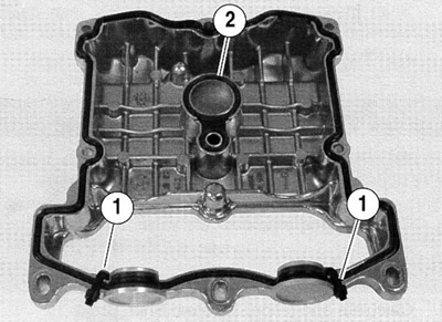
Figure 1-76. Cam cover gaskets: 1. Cable strap; 2. Spark plug hole gasket
28. See Figure 1-78. Apply a thin bead of silicone along both half-moon shaped recesses in cylinder head. Cam cover gasket must stay in place, a small amount of sealer, lightly applied will help.
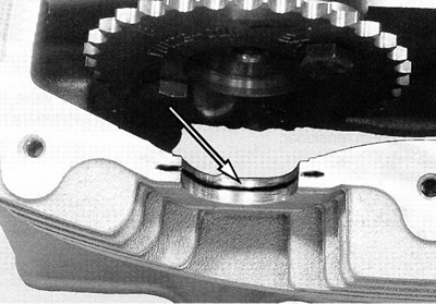
Figure 1-78. Silicone bead pattern in head recesses
29. Carefully install cam cover and gasket. Cable straps will allow the cam bore plug to be moved horizontally to clear cam drive gears.
30. Visually check to ensure spark plug hole gasket (2) is in place.
Note. See Figure 1-77. The seal of the spark plug hole gasket is correct when the tapered edge of the gasket is in the cam cover and the double lipped side of the rings is facing out to mate with the flat of the cylinder head.

Figure 1-77. Spark plug hole gasket (double lipped side)
31. Remove cable straps.
32. Place small cam cover in position.
33. See Figure 1-79. Insert GASKET ALIGNMENT TOOL (HD-45340).

Figure 1-79. Gasket alignment tool (H-D-45340)
34. See Figure 1-80. Insert fasteners in cam cover and tighten to 9.7 Nm (86 in-lbs) in sequence shown.
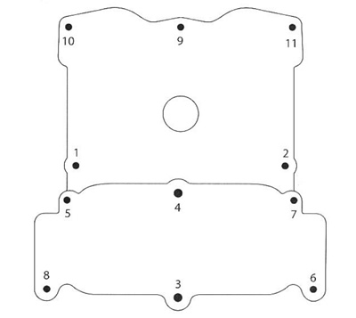
Figure 1-80. Cam cover torque sequence
35. See Figure 1-58. Tighten front motor mount fastener to 38 Nm (28 ft-lbs).
36. Position the main harness along the left side of the frame and install cable straps.
37. Install front cylinder and rear cylinder breather hoses.
38. Install p-clamp around the right side radiator hoses and tighten fastener to 9.7 Nm (86 in-lbs).
39. Connect ground strap to cam cover. Tighten to 9.7 Nm (86 in-lbs).
40. See Figure 1-81. Orient intake clamps as shown.
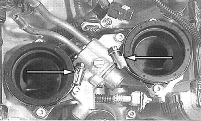
Figure 1-81. Intake clamps, throttle body removed
41. Install throttle body and tighten clamps.
42. See 1.19 Spark plug/coil. Install coils.
43. Attach the idle speed control (IAC) connector.
44. Attach the throttle position (TP) sensor.
45. Attach fuel lines.
- a. Insert fuel lines from injector back under frame and connect to fuel tank.
- b. Push connector onto fuel tank elbow until a "click" is heard.
- c. Install right angle connectors on rigid lines from injector. Push until a "click" is heard.
46. Install battery. See 1.7 Battery maintenance.
47. Install airbox assembly. See 1.4 Airbox and air filter.
