Note.
- Mark and record the valve lifter and shim locations so they can be reinstalled in their original positions.
- If there is no clearance, select a shim which is several sizes smaller and then measure the clearance.
To select a new shim which brings the valve clearance within the specified range, refer to the Valve Clearance Adjustment Charts.
Apply a thin coat of molybdenum disulfide grease to the valve lifters.
Install the camshafts. Be sure to time the camshafts properly (see Camshaft Installation).
Remeasure any valve clearance that was adjusted. Readjust if necessary.
Caution!
- Do not put shim stock under the shim. This may cause the shim to pop out at high rpm, causing extensive engine damage.
- Do not grind the shim. This may cause it to fracture, causing extensive engine damage.
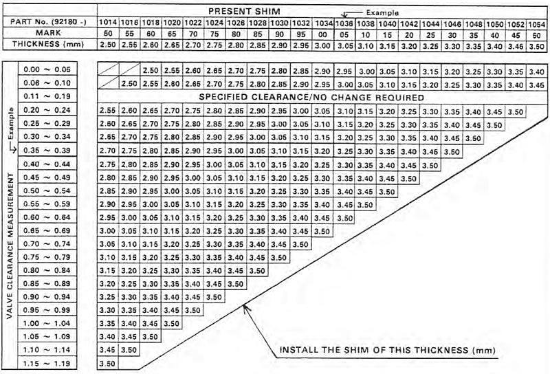
Valve clearance adjustment chart inlet valve

1. Measure the clearance (when engine is cold).
2. Check present shim size.
3. Match clearance In vertical column with present shim size in horizontal column.
4. Install the shim specified where the lines intersect. This shim will give the proper clearance.
Example:
Present shim is 3.05 mm
Measured clearance is 0.35 mm
Replace 3.05 mm shim with 3.25 mm shim.
5. Remeasure the valve clearance and readjust if necessary.
Valve clearance adjustment chart exhaust valve

1. Measure the clearance (when engine is cold).
2. Check present shim size.
3. Match clearance in vertical column with present shim size in horizontal column.
4. Install the shim specified where the lines intersect. This shim will give the proper clearance.
Example: Present shim is 3.10 mm.
Measured clearance is 0.40 mm.
Replace 3.10 mm shim with 3.2 mm shim.
5. Remeasure the valve clearance and readjust if necessary.
