
Cooling fan
Check
1. If the engine is overheating and the cooling fan isn't coming on, first check the cooling fan circuit fuse (see Chapter 9). If the fuse is good, check the fan switch as described below.
2. If the fan does not come on (and the fan switch is good), the fault lies in either the cooling fan motor or the relevant wiring. Test all the wiring and connections as described in Chapter 9, following the relevant Wiring Diagram. Disconnect the fan wiring connector and check that there is battery voltage at the black/blue or blue/black (according to model) wire terminal on the loom side of the connector with the ignition ON. If there is no voltage, check the wiring.
3. To test the cooling fan motor, on XL600V and XRV750 models remove the right-hand fairing side panel, and on XL650V models remove the fairing (see Chapter 8). Disconnect the fan wiring connector and the fan switch wiring connector (see illustrations). Using a 12 volt battery and two jumper wires with suitable connectors, connect the battery positive (+) lead to the black/blue or blue/black (according to model) wire terminal on the fan side of the wiring connector, and the battery negative H lead to the fan switch wiring connector. Once connected the fan should operate. It it does not. and the wiring Is all good, then the fan motor is faulty. Individual components are available for the fan assembly.
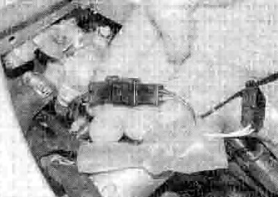
3.3a. Fan wiring connector - XL600V
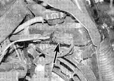
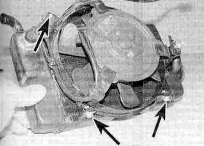
3.3b. Fan wiring connector (arrowed) -XL650V
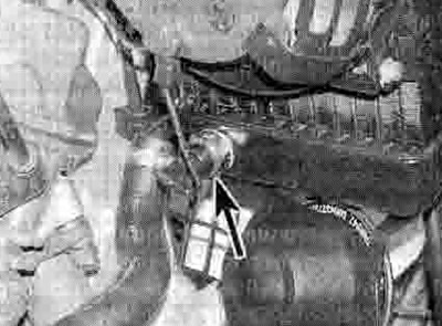
3.3c. Fan switch wiring connector (arrowed)
Replacement
Warning: The engine must be completely cool before carrying out this procedure.
4. Remove the right-hand radiator (see Section 6).
5. Disconnect the wiring connector from the fan switch (see illustration). Free the wiring from any clips.
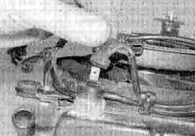
3.5. Disconnect the switch connector...
6. Undo the bolts securing the fan assembly to the radiator, noting that one of them also secures the earth (ground) wire (see Illustration).
3.6 ...then undo the bolts (arrowed) and remove the fan assembly
7. Unscrew the fan blade nut and remove the blade, noting how it locates. Undo the nuts on the front of the fan motor securing it to the shroud and separate them.
8. Installation is the reverse of removal. Apply a suitable non-permanent thread locking compound the fan blade nut and tighten it to the torque setting specified at the beginning of the Chapter. Also tighten the fan motor nuts to the specified torque. Do not forget to attach the earth (ground) cable to the radiator when fitting the fan assembly bolts.
9. Install the radiator (see Section 6).
Cooling fan switch
Check
10. If the engine is overheating and the cooling fan isn't coming on. first check the cooling fan circuit fuse (see Chapter 9). If the fuse is blown, check the fan circuit for a short to earth (see the wiring diagrams at the end of this book).
11. If the fuse Is good, on XL600V and XRV750 models remove the right-hand fairing side panel, and on XL650V models remove the lairing (see Chapter 8). Disconnect the wiring connector from the fan switch on the radiator (see illustration 3.3b). Using a jumper wire if necessary, connect the wire to earth (ground). Turn the ignition switch ON. The fan should come on. If it does, the fan switch is defective and must be replaced with a new one. If it does not come on, check for battery voltage at the switch wiring connector with the ignition ON. If voltage is present, test the fan motor itself (see above). If there is no voltage, check the wiring and connectors for a fault or break.
12. If the fan Is on the whole time, disconnect the wiring connector. The fan should stop. If it does, the switch is defective and must be replaced with a new one. If it doesn't, check the wiring between the switch and the fan for a short to earth, and the fan itself.
13. If the fan works but is suspected of cutting in at the wrong temperature, a more comprehensive test of the switch can be made as follows.
14. Remove the switch (see Steps 16 and 17). Fill a small heatproof container with coolant and place it on a stove. Connect the positive (+) probe of an ohmmeter to the terminal of the switch and the negative (-) probe to the switch body, and using some wire or other support suspend the switch in the coolant so that just the sensing portion and the threads are submerged (see illustration). Also place a thermometer capable of reading temperatures up to 110°C in the coolant so that its bulb is close to the switch. Note: None of the components should be allowed to directly touch the container.

3.14. Cooling fan switch testing set-up
15. Initially the ohmmeter reading should be very high Indicating that the switch is open (OFF). Heat the coolant, stirring it gently.
Warning: This must be done very carefully to avoid the risk of personal injury.
When the temperature reaches around 98 to 102°C the meter reading should drop to around zero ohms, indicating that the switch has closed (ON). Now turn the heat off. As the temperature falls below 93 to 97°C the meter reading should show infinite (very high) resistance, indicating that the switch has opened (OFF). If the meter readings obtained are different, or they are obtained at different temperatures, then the switch is faulty and must be replaced with a new one.
Replacement
Warning: The engine must be completely cool before carrying out this procedure.
16. Drain the cooling system (see Chapter 1).
17. Disconnect the wiring connector from the fan switch on the right-hand radiator (see illustration 3.3b). Unscrew the switch and withdraw it from the radiator. Discard the О-ring as a new one must be used.
18. Install the switch using a new О-ring and some suitable sealant on the upper portion of the threads, and tighten it to the torque setting specified at the beginning of the Chapter. Take care not to overtighten the switch as the radiator could be damaged.
19. Reconnect the switch wiring and refill the cooling system (see Chapter 1).