
Warning: If the engine has been running the exhaust system will be very hot. Allow the system to cool before carrying out any work.
Removal
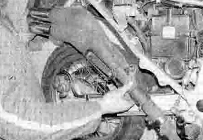
1. Remove the right-hand side panel, the belly-pan, on XL600V and XRV750 models the right-hand fairing side panel, and on XL650V models the fairing (see Chapter 8). Remove the heat shield, noting how it fits (see illustrations).
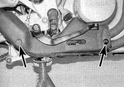
13.1a. Unscrew the bolts (arrowed)...
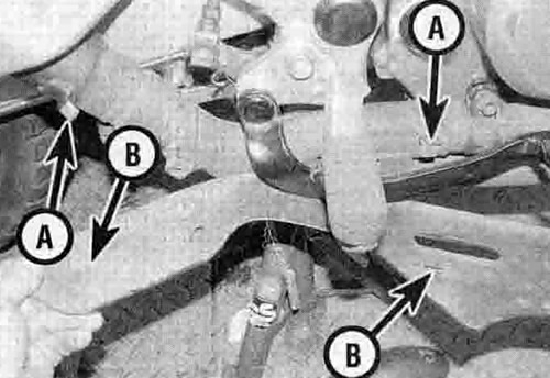
13.1b ...and remove the heatshield, noting how the tabs (A) locate in the slots (B) - XL600V shown

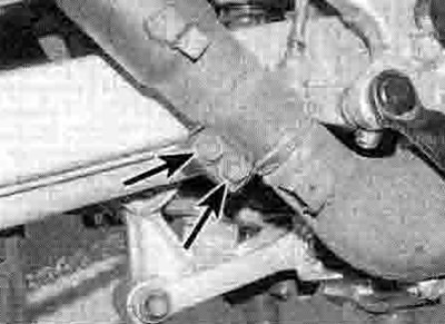
13.1c. On XL models, also remove the rear downpipe shield (arrowed) if required
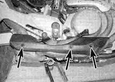
13.1d. The shield on the XL650V is secured by three bolts (arrowed)
2. Slacken the silencer clamp bolts, then unscrew the silencer mounting bolts and remove the silencer, noting how it fits (see illustrations). On XL models note the collar fitted with the front mounting bolt.
13.2a. On XL models, slacken the clamp bolts (arrowed)...

13.2b ...then unscrew the front bolt (arrowed)...

13.2c ...and the rear bolt (arrowed)...
13.2d ...and remove the silencer
13.2e. On XRV models, slacken the clamp bolt (arrowed)...

13.2f ...then unscrew the mounting bolts (arrowed) and remove the silencer
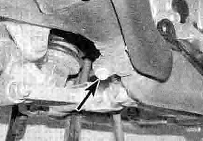
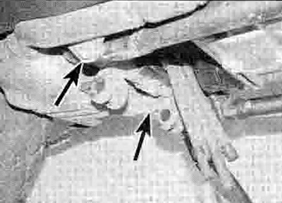
3. On XL650V models, slacken the front downpipe clamp bolt (see illustration). On all models unscrew the front downpipe flange retaining nuts from the cylinder head studs (see illustrations). Draw the flange off the studs, then twist the pipe so it is clear of the engine and remove it.
13.3a. Slacken the clamp bolt (arrowed)
13.3b. Front downpipe flange nuts (arrowed) - XL models
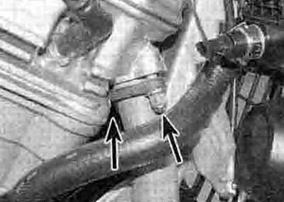
13.3c. Front downpipe flange nuts (arrowed) - XRV models
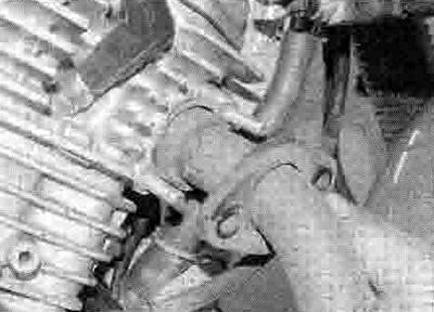
13.3d. Draw the flange off the studs...
13.3e ...and remove the pipe
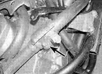
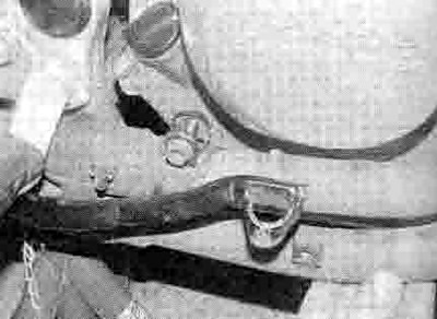
4. Unscrew the rear downpipe flange retaining nuts from the cylinder head studs. Slacken the rear downpipe clamp bolt, then twist the pipe so it is clear of the engine and remove it (see illustrations).
13.4a. Slacken the clamp bolt (arrowed)...
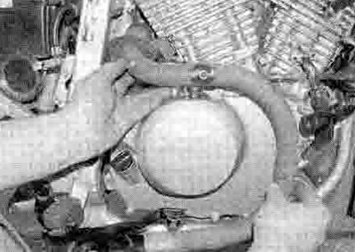
13.4b ...and remove the downpipe
5. Remove the gasket from each cylinder head, noting that the rear gasket is a smaller diameter than that of the front, and discard them as new ones must be fitted (see illustration).

13.5. Remove the gasket from each head
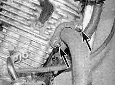
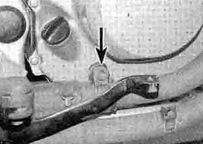
6. On XL650V models, if required, unscrew the collector box mounting bolts and remove the box. noting how it fits (see illustration).
13.6. Collector box mounting bolts (arrowed) - XL650V
7. Check the condition of the sealing rings between the components and replace them with new ones if they are damaged or deformed (see illustrations). Honda recommend always using new ones, but they can be difficult to remove, and unless they are damaged they are re-usable. It is too easy to damage a new one trying to Install it to make it worthwhile destroying a good one that is already installed.

13.7a. Dig out the old sealing ring...
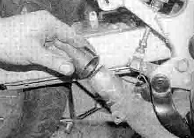
13.7b ...and fit a new one
Installation
8. Installation is the reverse of removal, noting the following:
- Use a new gasket in each cylinder head port (see illustration). Replace any damaged, deformed or deteriorated mounting rubbers with new ones.
- Use a new sealing ring between each component if required, bearing in mind the information in Step 7 above (see illustration 13.7b).
- Apply a smear of copper grease to all bolts to prevent them from seizing up.
- Leave all fasteners loose until the entire system has been installed, making alignment of the various sections easier. Tighten the silencer mounting last.
- Tighten the downpipe nuts to the torque setting specified at the beginning of the Chapter.
- Run the engine and check the system for leaks.
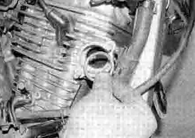
13.8. Fit a new gasket into each head