
2. To disassemble the valve components without the risk of damaging them, a valve spring compressor is absolutely essential. Make sure it is suitable for motorcycle work.
Disassembly
3. Before proceeding, arrange to label and store the valves along with their related components in such a way that they can be returned to their original locations without getting mixed up (see illustration). A good way to do this is to obtain a container which is divided into six compartments, and label each compartment with the location of a valve, i.e. left intake valve, right intake valve or exhaust valve. If a container is not available, use labelled plastic bags (an egg carton also does very well!).

14.3. Valve components: 1. Collets; 2. Spring retainer; 3. Inner spring; 4. Outer spring; 5. Spring seat; 6. Stem seal; 7. Valve
4. Clean all traces of old gasket material from the cylinder head. If a scraper is used, take care not to scratch or gouge the soft aluminium.
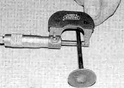
5. Compress the valve spring on the first valve with a spring compressor, making sure it is correctly located onto each end of the valve assembly (see illustrations). On the underside of the head make sure the plate on the compressor only contacts the valve and not the soft aluminium of the head - if the plate is too big for the valve, use a spacer between them. Do not compress the springs any more than is absolutely necessary. Remove the collets, using either needle-nose pliers, tweezers, a magnet or a screwdriver with a dab of grease on it (see illustration). Carefully release the valve spring compressor and remove it. Remove the spring retainer.

14.5a. Make sure the compressor locates correctly on the valve...

14.5b ...and the spring retainer

14.5c. Remove the collets as described

14.5d. Remove any burrs (1) if the valve stem (2) won't pull through the guide
noting which way up it fits (see illustration 14.28c). Remove the springs, noting that the closer wound coils are at the bottom (see illustrations 14.28a and 14.3). Press down on the top of the valve stem and draw the valve out from the underside of the head (see Illustration 14.27b). If the valve binds in the guide (won't pull through), push it back into the head and deburr the area around the collet groove with a very fine file or whetstone (see illustration).
6. Once the valve has been removed and labelled, pull the valve stem oil seal off the top of the valve guide and discard it (the old seals should never be reused) (see illustration). Now remove the spring seat (see illustration). The seat is difficult to get hold of, so either use a small magnet or turn the head upside down and tip it out, taking care not to lose it.

14.6a. Pull the oil seal off the top of the guide...

14.6b ...then remove the spring seat
7. Repeat the procedure for the remaining valves. Remember to keep the parts for each valve together and in order so they can be reinstalled in the same location.
8. Next, clean the cylinder head with solvent and dry it thoroughly. Compressed air will speed the drying process and ensure that all holes and recessed areas are reached.
9. Clean all of the valve springs, collets, retainers and spring seats with solvent and dry them thoroughly. Do the parts from one valve at a time so they don't get mixed up.
10. Scrape off any deposits that may have formed on the valve, then use a motorised wire brush to remove deposits from the valve heads and stems. Again, make sure the valves do not get mixed up.
Inspection
11. Inspect the head very carefully for cracks and other damage. If cracks are found, a new head will be required. Check the camshaft bearing surfaces for wear and evidence of seizure. Check the camshafts and holders for wear as well (see Section 9).
12. Using a precision straight-edge and a feeler gauge set to the warpage limit listed in the specifications at the beginning of the Chapter, check the head gasket mating surface for warpage. Refer to Tools and Workshop Tips in the Reference section for details of how to use the straight-edge.
13. Examine the valve seats in the combustion chamber. If they are pitted, cracked or burned, the head will require work beyond the scope of the home mechanic. Measure the valve seat width and compare it to this Chapter's Specifications (see illustration). If it exceeds the service limit, or if it varies around its circumference, overhaul is required.

14.13. Measure the valve seat width with a ruler (or for greater precision use a Vernier caliper)
14. Measure the valve stem diameter (see illustration). Clean the valve guides using a guide reamer to remove any carbon build-up, then measure the Inside diameters of the guides (at both ends and in the centre of the guide) with a small bore gauge, then measure the gauge with a micrometer (see illustration). Measure the guides at the ends and at the centre to determine if they are worn in a bell-mouth pattern (more wear at the ends). Subtract the stem diameter from the valve guide diameter to obtain the valve stem-to-guide clearance. If the stem-to-guide clearance is greater than listed in this Chapter's Specifications, renew whichever components are worn beyond their specification limits. If the valve guide is within specifications, but is worn unevenly, it should be renewed.
14.14a. Measure the valve stem diameter with a micrometer...

14.14b ...then measure the guide bore using a small hole gauge and micrometer
15. Carefully inspect each valve face, stem and collet groove area for cracks, pits and burned spots (see illustration).

14.15. Check the valve face (A), stem (B) and collet groove (C) for signs of wear and damage
16. Rotate the valve and check for any obvious indication that it is bent, in which case it must be replaced with a new one. Check the end of the stem for pitting and excessive wear. The presence of any of the above conditions indicates the need for valve servicing. The stem end can be ground down, provided that the amount of stem above the collet groove after grinding is sufficient.
17. Check the end of each valve spring for wear and pitting. Measure the spring free lengths and compare them to the Specifications (see illustration). If any spring is shorter than specified it has sagged and must be replaced with a new one. Also place the spring upright on a flat surface and check it for bend by placing a ruler against it, or alternatively lay it against a set square (see illustration). It the bend in any spring is excessive, it must be replaced with a new one.

14.17a. Measure the free length of the valve springs

14.17b. Check the valve springs for squareness
18. Check the spring seats, retainers and collets for obvious wear and cracks. Any questionable parts should not be reused, as extensive damage will occur in the event of failure during engine operation.
19. If the inspection indicates that no overhaul work is required, the valve components can be reinstalled in the head.
Reassembly
20. Unless a valve service has been performed, before installing the valves in the head they should be ground in (lapped) to ensure a positive seal between the valves and seats. This procedure requires coarse and fine valve grinding compound and a valve grinding tool (either hand-held or drill driven). If a grinding tool is not available, a piece of rubber or plastic hose can be slipped over the valve stem (after the valve has been installed in the guide) and used to turn the valve.
21. Apply a small amount of coarse grinding compound to the valve face, and some molybdenum disulphide oil (a 50/50 mixture of molybdenum disulphide grease and engine oil) to the valve stem, then slip the valve into the guide (see illustrations).
Note: Make sure each valve is installed in its correct guide and be careful not to get any grinding compound on the valve stem.

14.21a. Apply the lapping compound very sparingly, in small dabs, to the valve face only

14.21b. Lubricate the stem and insert the valve in the guide
22. Attach the grinding tool (or hose) to the valve and rotate the tool between the palms of your hands. Use a back-and-forth motion (as though rubbing your hands together) rather than a circular motion (i.e. so that the valve rotates alternately clockwise and anticlockwise rather than in one direction only) (see illustration). If a motorised tool is being used, take note of the correct drive speed for it - If your drill runs too fast and is not variable, use a hand tool instead. Lift the valve off the seat and turn it at regular intervals to distribute the grinding compound properly. Continue the grinding procedure until the valve face and seat contact area is of uniform and correct width, and unbroken around the entire circumference (see illustration and 14.13).

14.22a. Rotate the valve grinding tool back and forth between the palms of your hands

14.22b. The valve face and seat should show a uniform unbroken ring and the seat should be the specified width all the way round
23. Carefully remove the valve from the guide and wipe off all traces of grinding compound, making sure none gets in the guide. Use solvent to clean the valve and wipe the seat area thoroughly with a solvent soaked cloth.
24. Repeat the procedure with fine valve grinding compound, then repeat the entire procedure for the remaining valves.
25. Working on one valve at a time, lay the spring seat in place in the cylinder head, making sure the shouldered side faces up (see illustration).

14.25. Fit the spring seat, making sure it is the correct way up
26. Fit a new valve stem seal onto the guide, using a stem seal fitting tool or an appropriate size deep socket to push the seal over the end of the valve guide until it is felt to clip into place (see illustrations). Don't twist or cock the seal, or it will not seal properly against the valve stem. Also, don't remove it again or it will be damaged.

14.26a. Fit a new valve stem seal...

14.26b ...using a deep socket or special tool to press it squarely into place
27. Coat the valve stem with molybdenum disulphide oil (a 50/50 mixture of molybdenum disulphide grease and engine oil), then install It into its guide, rotating it slowly to avoid damaging the seal (see illustrations). Check that the valve moves up and down freely in the guide.

14.27a. Lubricate the stem...

14.27b ...and slide the valve into its correct location
28. Next, install the inner and outer springs, with the closer-wound coils facing down into the cylinder head (see illustrations). Fit the spring retainer, with its shouldered side facing down so that it fits into the top of the springs (see illustration).

14.28a. Fit the inner valve spring...

14.28b ...and the outer valve spring ...

14.28c ...then fit the spring retainer
29. Compress the valve spring with a spring compressor, making sure It is correctly located onto each end of the valve assembly (see illustrations 14.5a and b). On the underside of the head make sure the plate on the compressor only contacts the valve and not the soft aluminium of the head - if the plate is too big for the valve, use a spacer between them. Do not compress the springs any more than is necessary to slip the collets into place. Apply a small amount of grease to the collets to help hold them In place (see illustration 14.5c). Locate each collet in turn into the groove in the valve stem, then carefully release the compressor, making sure the collets seat and lock as you do (see illustration). Check that the collets are securely locked in the retaining groove (see illustration).

14.29a. Make sure both collets lock into the groove as the compressor is released...

14.29b ...and remain in place when it is removed
30. Support the cylinder head on blocks so the valves can't contact the workbench top, then very gently tap the top of the valve stem with a brass drift. This will help seat the collets m the groove. If you don't have a brass drift, fit the shim into its recess In the top of the valve spring retainer and use a soft-faced hammer and a piece of wood as an interface
Check for proper sealing of the valves by pouring a small amount of solvent into each of the valve ports. If the solvent leaks past any valve into the combustion chamber area the valve grinding operation on that valve should be repeated.
31. Repeat the procedure for the remaining valves. Remember to keep the parts for each valve together, and separate from the other valves, so they can be reinstalled in the same location. After the cylinder head and camshafts have been installed, check the valve clearances and adjust as required (see Chapter 1).