Construction
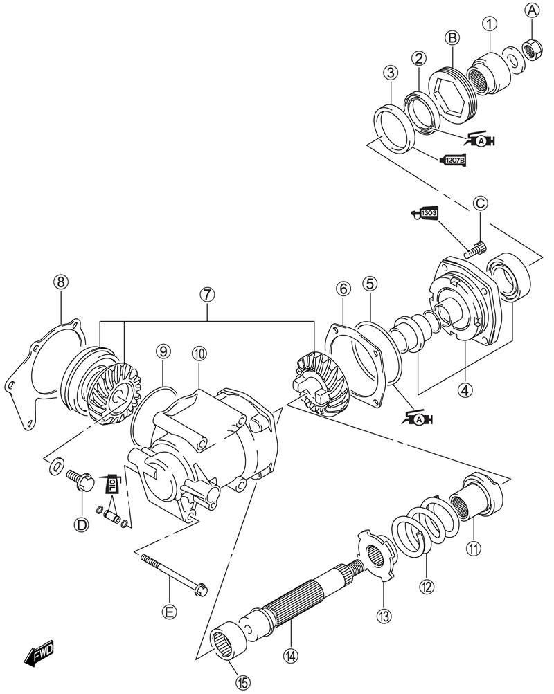
1. Driven bevel gear coupling; 2. Oil seal; 3. Oil seal housing; 4. Bearing housing set; 5. O-ring; 6. Shims; 7. Secondary bevel gear set; 8. Shims; 9. O-ring; 10. Secondary gear case; 11. Output cam dog; 12. Damper spring; 13. Spring cam stopper; 14. Driven bevel gear shaft; 15. Driven bevel gear bearing; А. Driven bevel gear coupling nut; В. Secondary driven bearing stopper; С. Secondary driven bearing housing bolt; D. Secondary drive gear bolt; Е. Secondary driven gear case bolt
| ITEM | Nm | kgf·m | lb·ft |
| А | 95 | 9.5 | 68.5 |
| В | 105 | 10.5 | 76.0 |
| ITEM | Nm | kgf·m | lb·ft |
| С | 28 | 2.8 | 20.0 |
| D | 145 | 14.5 | 105.0 |
| ITEM | Nm | kgf·m | lb·ft |
| Е | 26 | 2.6 | 19.0 |
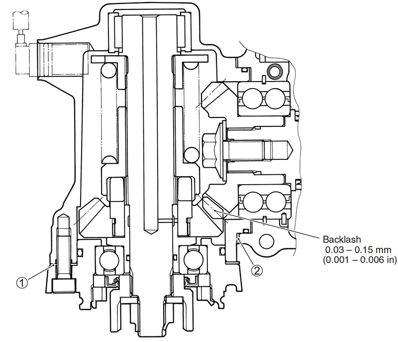
Adjust backlash by selecting shims. (Use two pieces of shims.) Shim 1 size table
| Part number | Thickness |
| 24945-26D00-030 | 0.30 mm (0.012 in) |
| 24945-26D00-035 | 0.35 mm (0.014 in) |
| 24945-26D00-040 | 0.40 mm (0.016 in) |
| 24945-26D00-050 | 0.50 mm (0.020 in) |
| 24945-26D00-060 | 0.60 mm (0.024 in) |
The shims 1 are available as a set (24945-26810).
Shim 2 size table
| Part number | Thickness |
| 24935-48G00-040 | 0.40 mm (0.016 in) |
| 24935-48G00-045 | 0.45 mm (0.018 in) |
| 24935-48G00-050 | 0.50 mm (0.020 in) |
| 24935-48G00-055 | 0.55 mm (0.022 in) |
| 24935-48G00-060 | 0.60 mm (0.024 in) |
| 24935-48G00-065 | 0.65 mm (0.026 in) |
| 24935-48G00-070 | 0.70 mm (0.028 in) |
| 24935-48G00-075 | 0.75 mm (0.030 in) |
| 24935-48G00-080 | 0.80 mm (0.031 in) |
The shims 2 are available as a set (24935-48810).
Removal
The secondary bevel gear service requires engine removal and disassembly. Refer to the engine removal and the engine disassembly sections for secondary bevel gear assembly removal.
Engine removal (3-3).
Disassembly
Secondary drive bevel gear (З-28)
Secondary driven bevel gear
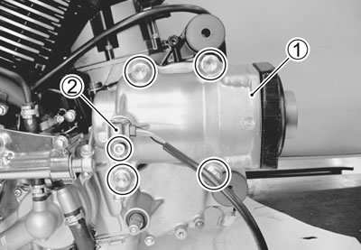
- Remove the secondary gear case 1 and speedometer sensor 2.
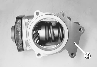
- Remove the shims 3.
- Remove the secondary driven gear assembly 4.
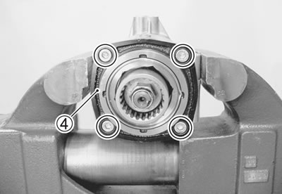
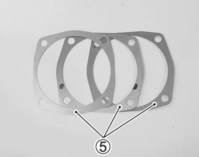
- Remove the shims 5.
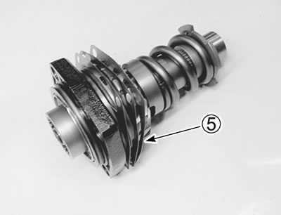
- Using a chisel, unlock the nut.
- Remove the driven bevel gear coupling nut with the special tool.
- 09924-64510: Final drive gear coupling holder
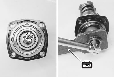
- Remove the washer 6 and the driven bevel gear coupling 7.
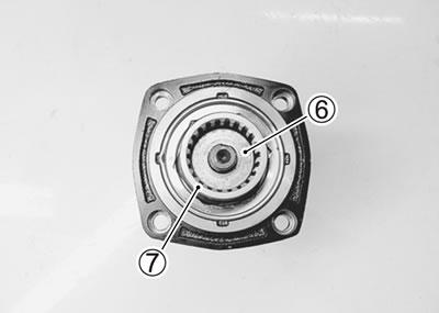
- Using a chisel, unlock the nut.
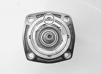
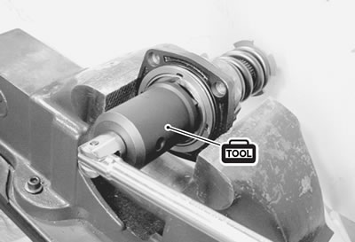
- Remove the bearing stopper with the special tool.
- 09924-41830: Bearing retainer wrench
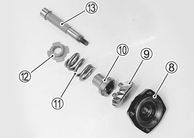
- Remove the bearing housing 8, secondary driven gear 9, output cam dog 10, damper spring 11, spring cam stopper 12 and shaft 13.
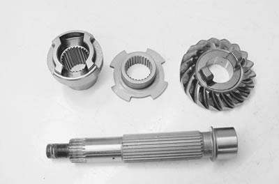
Inspection
- Driven bevel gear damage or wear
- Improper tooth contact
- Output cam dog wear or damage
- Shaft damage or wear.
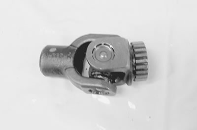
- Universal joint spline damage or wear
Bearing/oil seal
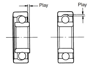
- Rotate the bearing inner race by finger to inspect for abnormal play, noise and smooth rotation while the bearings are in the bearing housing and secondary gear case.
- Replace the bearing in the following procedure if there is anything unusual.
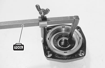
- Remove the oil seal with the special tool.
- 09913-50121: Oil seal remover
Caution: The removed oil seal must be replaced with a new one.
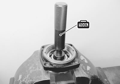
- Remove the driven gear stopper with the special tool.
- 09913-70210: Bearing installer set (30 mm)
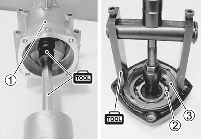
- Remove the bearings (1, 2) and oil seal housing 3 with the special tools.
- 09921-20240: Bearing remover set (30 mm)
- 09941-64511: Bearing remover
- 09930-30104: Sliding shaft
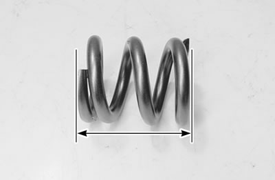
Damper spring
- Measure the free length of the damper spring. If the length is shorter than the service limit, replace the spring with a new one. Damper spring free length
- Service limit: 64.6 mm (2.54 in)
Speedometer sensor (10-37).
Reassembly
- Reassemble the secondary driven gear in the reverse order of disassembly.
- The following steps require special attention or precautionary measures should be taken.
Bearing and oil seal housing
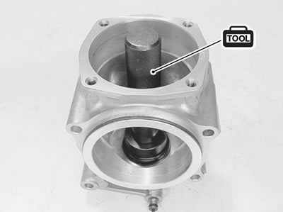
- Install the bearing with the special tool.
- 09913-70210: Bearing installer set (68 mm)
Note: When installing the bearing, stamped mark on the bearing must face outside.
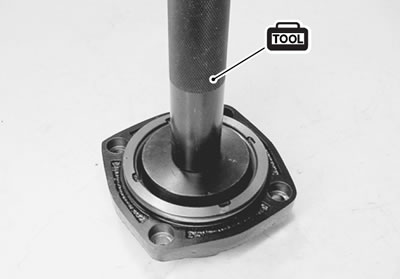
- Install the bearing with the special tool.
- 09913-70210: Bearing installer set (42 mm)
Note: When installing the bearing, stamped mark on the bearing must face outside.
- Apply SUZUKI BOND to the mating surface of the bearing housing and oil seal housing.
- 99000-31140: SUZUKI BOND "1207B" or equivalent
Note:
- Make surfaces free from moisture, oil, dust and other foreign materials.
- Take extreme care not to apply any BOND to the bearing.
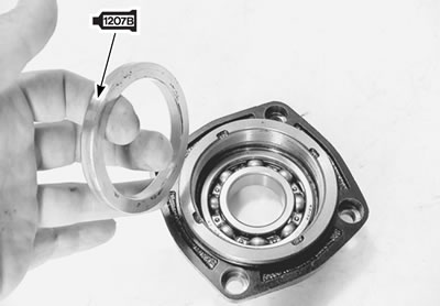
Driven gear stopper
- Install the driven gear stopper with the special tool.
- 09913-70210: Bearing installer set (52 mm)
Note: The chamter side А of driven gear stopper faces to the bearing.
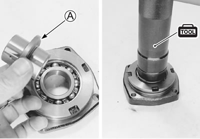
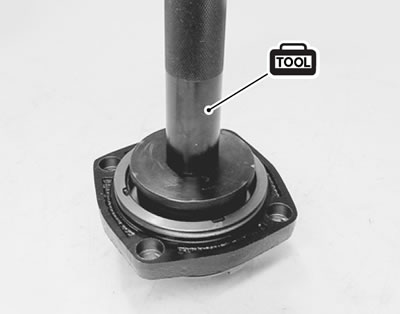
- Install the oil seal with the special tool.
- 09913-70210: Bearing installer set (62 mm)
- Apply SUZUKI SUPER GREASE "A" to the oil seal lip.
- 99000-25010: SUZUKI SUPER GREASE "A" or equivalent
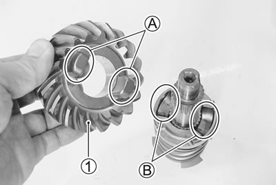
Secondary driven bevel gear
- Install the secondary driven gear 1.
Note: When install the secondary driven gear, fit the convex parts А of the secondary driven gear onto the concave parts В of the output cam dog.
- Tighten the bearing stopper to the specified torque with special tool.
Secondary driven gear bearing stopper: 105 Nm (10.5 kgf·m, 76.0 lb·ft)
- 09924-41830: Bearing retainer wrench
- Lock the bearing stopper with a center punch.
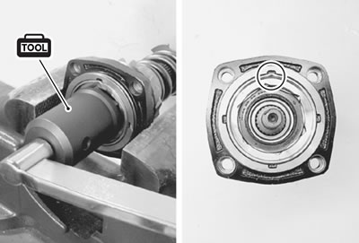
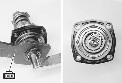
- Tighten the coupling nut to the specified torque with the special tool.
Secondary driven bevel gear coupling nut: 95 Nm (9.5 kgf·m, 68.5 lb·ft)
- 09924-64510: Final drive coupling holder
- Lock the coupling nut with a center punch.
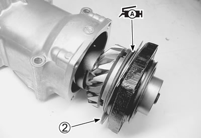
- Install the shims 2. (4-12)
- Apply SUZUKI SUPER GREASE "A" to the O-ring.
- 99000-25010: SUZUKI SUPER GREASE "A" or equivalent
Caution: Use a new O-ring to prevent to oil leakage.
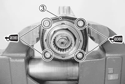
- Install the secondary driven gear assembly 3.
- Apply a small quantity of the THREAD LOCK SUPER to the bearing housing bolts and tighten it to the specified torque.
- 99000-32030: THREAD LOCK SUPER "1303" or equivalnet
Secondary driven bering housing bolt: 28 Nm (2.8 kgf·m, 20.0 lb·ft)
- Install the shims 4. (4-12)
- Install the secondary gear case. (3-90)
- Install the speedometer sensor. (10-37)
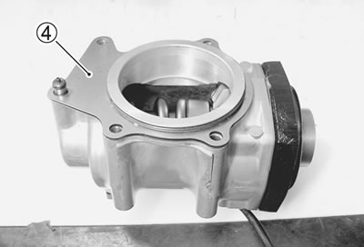
Secondary gear shims adjustment
Backlash
- Install the secondary driven gear assembly and secondary gear case with removed shims. (3-79 and 4-9)
Note: Do not install the O-ring on the driven gear housing at this stage. O-ring is installed after backlash and tooth contact are correct.
- Tighten the secondary driven gear case bolts to the specified torque.
Secondary driven gear case bolt: 26 Nm (2.6 kgf·m, 19.0 lb·ft)
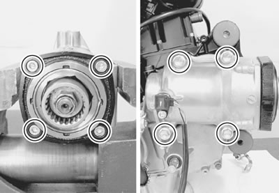
- Measure the backlash as follows.
- Install the backlash measuring tool on the driven bevel gear coupling, and set-up a dial gauge as shown in photo.
- 09924-34510: Backlash measuring tool (27 - 50 mm)
- 09900-20607: Dial gauge (1/100 mm, 10 mm)
- 09900-20701: Magnetic stand
- Adjust the dial gauge so that it touches the backlash measuring tool arm at the mark; hold the secondary drive bevel gear securely, and turn the secondary driven bevel gear coupling slightly in each direction, reading the total backlash on the dial gauge.
Secondary bevel gear backlash: 0.03 - 0.15 mm (0.001 - 0.006 in)
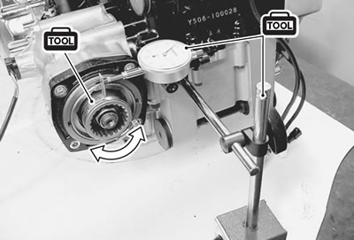
- If the backlash is not within specification, the shims (Driven bevel gear side) must be changed and the backlash should be re-checked until correct.
Refer to the chart for appropriate changes.
Note: When changing the shims (Driven bevel gear side), measure the thickness of old shims. Using the thickness of the old shims as a guide, adjust the backlash by referring to the chart.
| Backlash | Shim adjustment |
| Under 0.03 mm (0.001 in) | Increase shim thickness |
| 0.03 - 0.15 mm (0.001 - 0.006 in) | Correct |
| Over 0.15 mm (0.006 in) | Decrease shim thickness |
Driven bevel gear side
| Part number | Shim thickness |
| 24945-26D00-030 | 0.30 mm (0.012 in) |
| 24945-26D00-035 | 0.35 mm (0.014 in) |
| 24945-26D00-040 | 0.40 mm (0.016 in) |
| 24945-26D00-050 | 0.50 mm (0.020 in) |
| 24945-26D00-060 | 0.60 mm (0.024 in) |
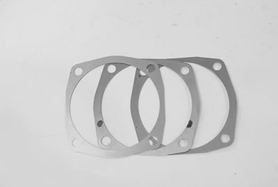
Note: The shims (driven bevel gear side) are available as a set (24945-26810).
Tooth contact
After bringing the backlash within specification by changing the secondary driven bevel gear shims, it will be necessary to check tooth contact.
- Remove the secondary gear case. (4-4)
- Clean and degrease the secondary drive bevel gear teeth, and apply a coating of machinist's layout dye or paste to several teeth.
- Reinstall the secondary gear case, with removed shims.
- Rotate the secondary driven bevel gear coupling several turns in both directions.
- Remove the secondary gear case from the crankcase, and observe the tooth contact pattern made in the dye or paste.
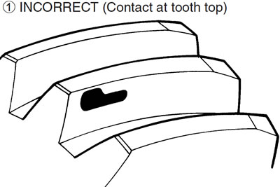
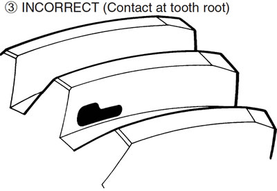
- Compare the tooth contact pattern to the examples as shown in 1, 2 and 3.
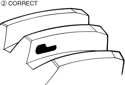
- If tooth contact is found to be incorrect, the shims of the secondary drive bevel gear and secondary driven bevel gear must be changed, tooth contact should be re-checked until correct.
Caution: After the tooth contact adjustment is made, the backlash must be re-checked, as it may change. Refer to the backlash checking sub-section, and readjust until both backlash and tooth contact are correct.
| Tooth contact | Shim adjustment |
| Contact at tooth top 1 | Decrease thickness of shims 4 or 5 |
| Contact at tooth root 3 | Increase thickness of shims 4 or 5 |
Shim specifications
Drive bevel gear side
| Part number | Thickness |
| 24935-48G00-040 | 0.40 mm (0.016 in) |
| 24935-48G00-045 | 0.45 mm (0.018 in) |
| 24935-48G00-050 | 0.50 mm (0.020 in) |
| 24935-48G00-055 | 0.55 mm (0.022 in) |
| 24935-48G00-060 | 0.60 mm (0.024 in) |
| 24935-48G00-065 | 0.65 mm (0.026 in) |
| 24935-48G00-070 | 0.70 mm (0.028 in) |
| 24935-48G00-075 | 0.75 mm (0.030 in) |
| 24935-48G00-080 | 0.80 mm (0.031 in) |
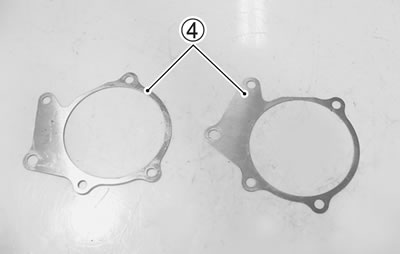
Note: The shims (drive bevel gear side) are available as a set (24935-48810).
Driven bevel gear side
| Part number | Shim thickness |
| 24945-26D00-030 | 0.30 mm (0.012 in) |
| 24945-26D00-035 | 0.35 mm (0.014 in) |
| 24945-26D00-040 | 0.40 mm (0.016 in) |
| 24945-26D00-050 | 0.50 mm (0.020 in) |
| 24945-26D00-060 | 0.60 mm (0.024 in) |
Note: The shims (driven bevel gear side) are available as a set (24945-26810).
