- Drain engine oil. (2-17)
- Drain engine coolant. (2-20)
- Remove the frame side covers. (9-5)
- Remove the fuel tank. (6-3)
- Remove the frame head covers and radiator covers. (9-6)
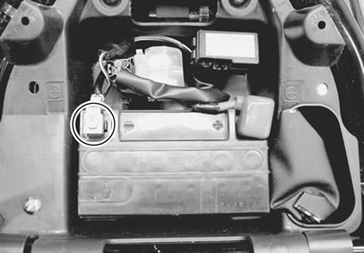
- Disconnect the battery lead wire.
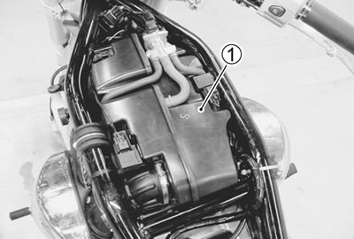
- Remove the air cleaner chamber 1. (6-13)
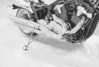
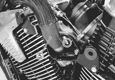
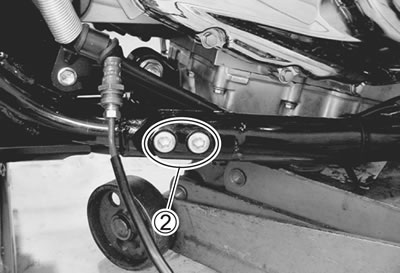
- Remove the exhaust pipes and mufflers 2. (7-8)
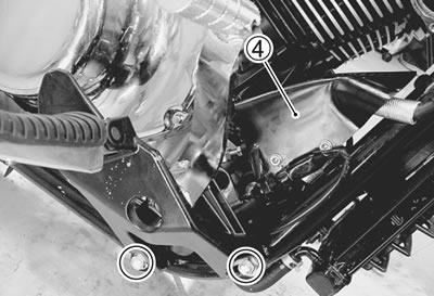
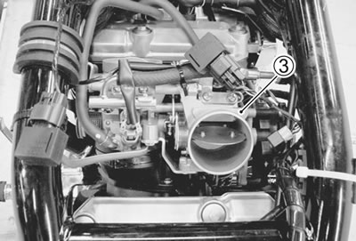
- Remove the throttle body 3. (6-15)
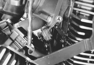
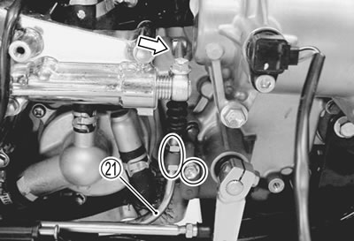
- Disconnect the ECT sensor lead wire coupler 4.
Disconnect the ignition coil/plug cap lead wire couplers and remove the ignition coils/plug caps. (2-13 and 2-14)
Caution:
- Do not remove the ignition coil/plug cap before disconnecting its coupler.
- Do not pry up the ignition coil/plug cap with a screw driver or a bar to avoid its damage.
- Be careful not to drop the ignition coil/plug cap to prevent its short or open circuit.
- Disconnect the spark plug caps. (2-13 and 2-14)
- Disconnect the radiator inlet hose 5.
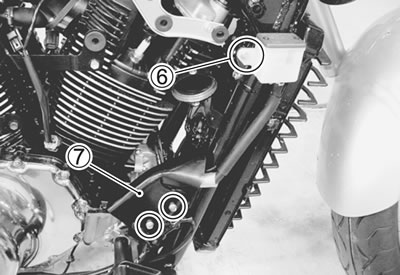
- Remove the rear brake fluid reservoir mounting bolt 6.
- Remove the master cylinder cover 7.
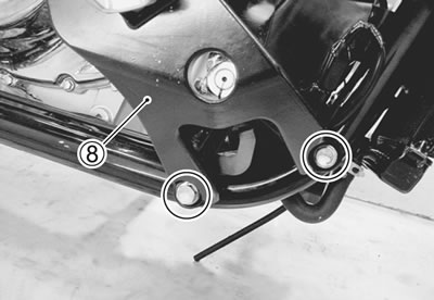
- Remove the right footrest 8.
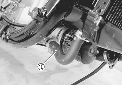
- Disconnect the oil cooler hose 10.
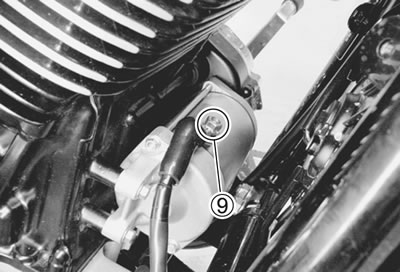
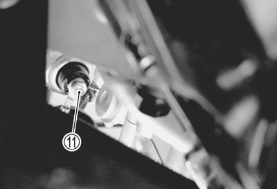
- Remove the oil pressure switch lead wire 9.
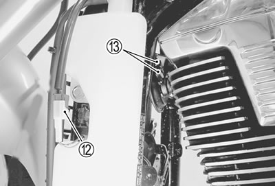
- Disconnect the cooling fan coupler 12 and horn lead wire couplers 13.
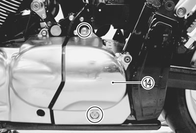
- Remove the left frame lower side cover 14.
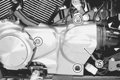
- Remove the secondary gear case cover 15.
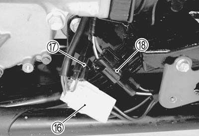
- Disconnect the generator lead wire coupler 16.
- Disconnect the CKP sensor lead wire coupler 17.
- Disconnect the regulator/rectifier lead wire coupler 18.
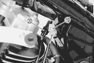
- Disconnect the side-stand switch lead wire coupler 19.
- Disconnect the speedometer sensor lead wire coupler 20.
- Remove the clutch cable 21.
- Support the engine with an engine jack.
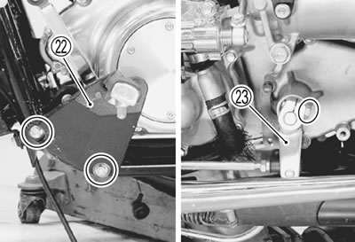
- Remove the left footrest 22 and gearshift lever 23.
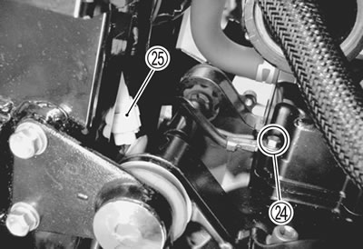
- Remove the ground lead wire 24.
- Disconnect the GP switch lead wire coupler 25.
- Remove the engine mounting bolt and nut.
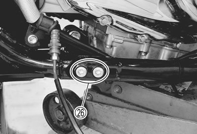
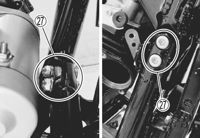
- Slightly move the frame down tube by removing its bolts 26, bolts and nuts 27.
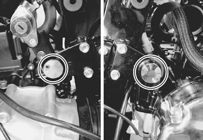
- Remove the caps.
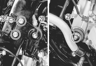
- Remove the engine mounting bracket bolts 28.
- Remove the engine mounting bolts and nuts 29.
- Remove the the engine assembly.
Engine installation
Install the engine in the reverse order of engine removal. Pay attention to the following points:
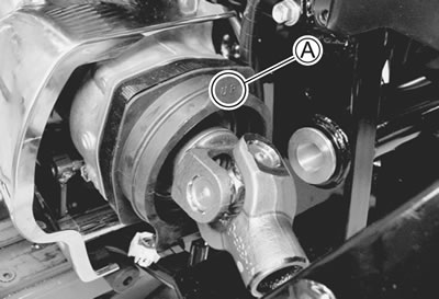
- Install the boot and universal joint.
Note: Make sure that the "UP" mark А faces up.
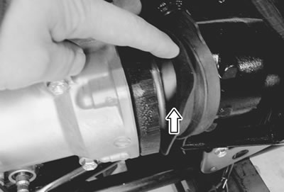
- Gradually raise the engine, and then engage the secondary driven gear shaft to the universal joint.
- Properly fit the boot onto the engine and the swingarm.
Caution: Be careful not to catch the wiring harness between the frame and the engine.
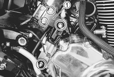
- Install the engine mounting bracket 1 and tighten it bolts to the specified torque.
Engine mounting bracket bolt (rear): 23 Nm (2.3 kgf·m, 16.5 lb·ft)
- Install the engine mounting bolts and nuts and tighten to the specified torque. (3-11)
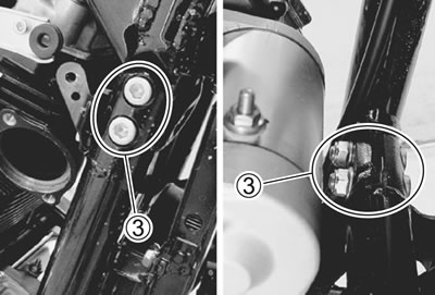
- Install the frame down tube and tighten the bolts 2, bolts and nuts 3 to the specified torque.
Note: The frame down tube nuts are self-locking. Once the nuts have been removed, they are no longer of any use.
Frame down tube bolt: 50 Nm (5.0 kgf·m, 36.0 lb·ft)
- Install the engine mounting bolt and nut and tighten to the specified torque. (3-11)
Note: The engine mounting nuts are self-locking. Once the nut has been removed, they are no longer of any use.
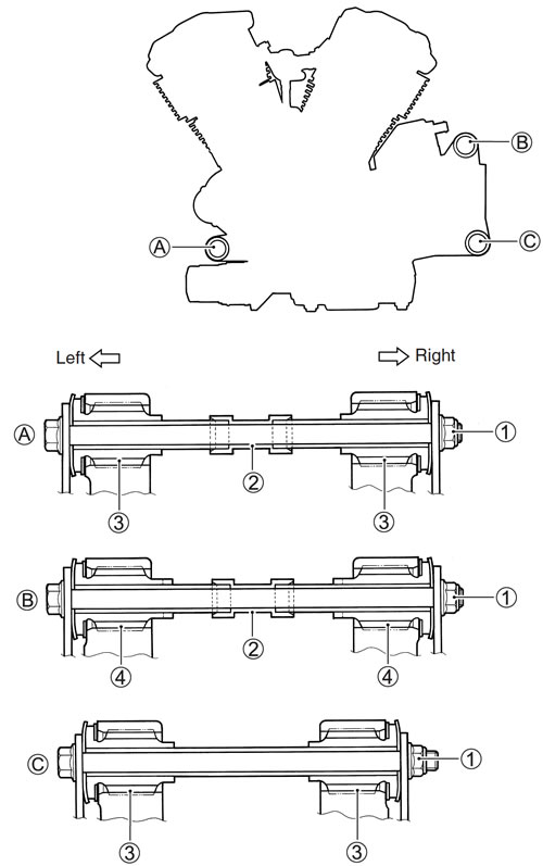
1. Engine mounting nut; 2. Spacer; 3. Bushing; 4. Bushing
| ITEM | Nm | kgf·m | Ibft |
| 1 | 55 | 5.5 | 40.0 |
- Install the gearshift lever and tighten the mounting bolts to the specified torque.
Left front footrest bolt: 50 Nm (5.0 kgf·m, 36.0 lb·ft)
- Footrest in the correct position.
Gearshift lever height А
Standard: 45 - 55 mm (1.8 - 2.2 in)

- Tighten the right front footrest mounting bolts to the specified torque.
Right front footrest bolt: 60 Nm (6.0 kgf·m, 43.5 lb·ft)
- Install the rear brake master cylinder cover 4. (9-72)