Caution: Identify the position of each removed part. Organize the parts in their respective groups (e.g., intake, exhaust) so that they can be reinstalled in their original positions.
- Remove the front and rear spark plugs.
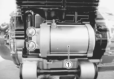
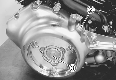
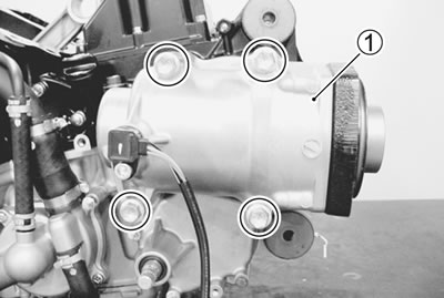
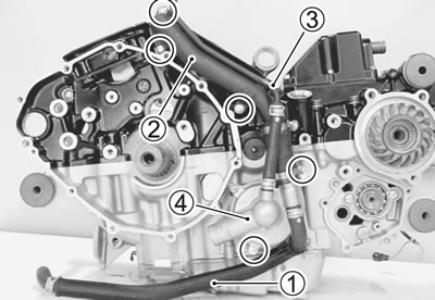
Starter motor
- Remove the starter motor 1.
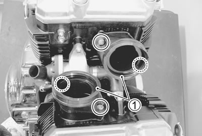
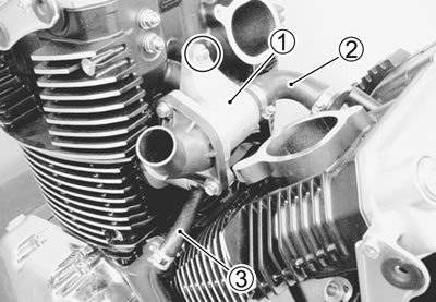
Intake pipe
- Remove the front and rear intake pipes 1.
Thermostat
- Remove the thermostat assembly 1 and disconnect the water hoses (2, 3).
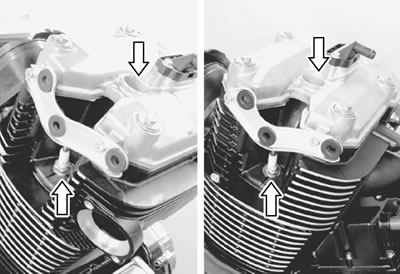
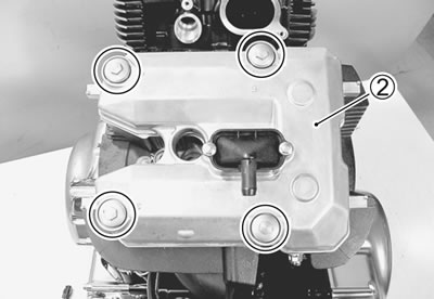
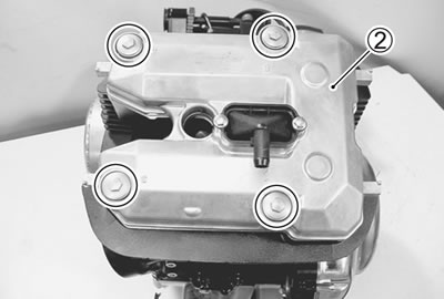
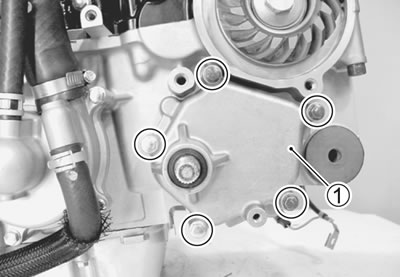
Rear cylinder head cover
- Remove the right and left head cover brackets 1.
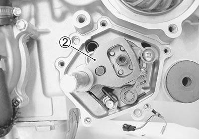
- Remove the rear cylinder head cover 2 and its gasket.
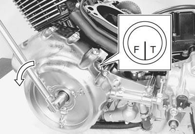
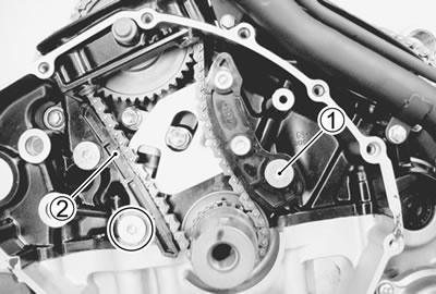
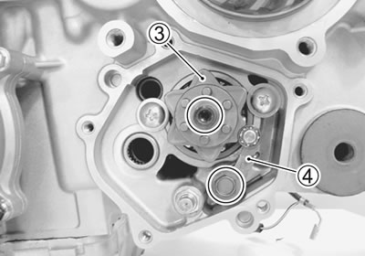
Rear camshaft
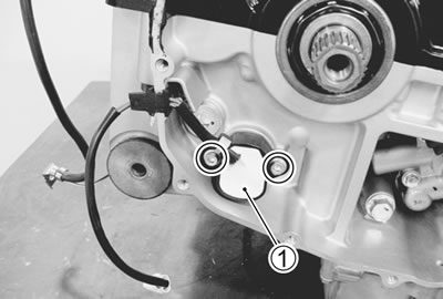
- Remove the generator cover cap 1.
- Remove the valve timing inspection plug 2 and generator cover plug 3.
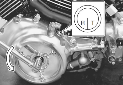
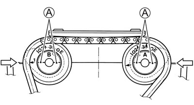
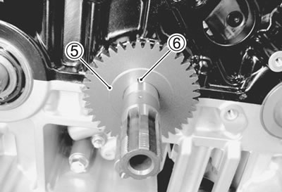
- Turn the crankshaft to bring the "R I T" line on generator rotor to the index mark of the valve inspection hole and also to bring the cams to the position as shown.
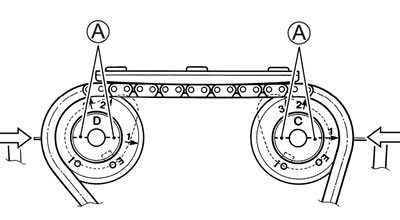
Note: At the above condition, the rear cylinder is at TDC of compression stroke and also the engraved lines А on the camshafts are parallel with the mating surface of the cylinder head cover.
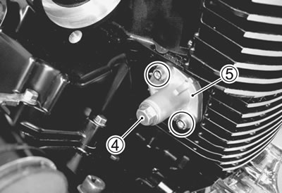
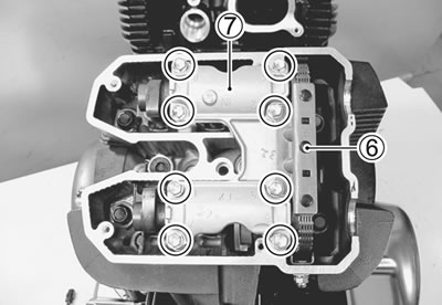
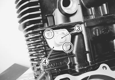
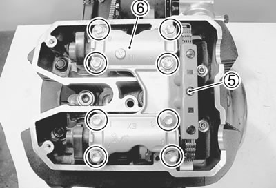
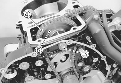
- Remove the cam chain tension adjuster cap bolt 4 and spring.
- Remove the rear cam chain tension adjuster No. 2 5 and gasket.
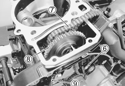
- Remove the cam chain guide No. 3 6.
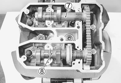
- Remove the camshaft journal holder 7.
- Remove the dowel pins.
Caution: Be sure to loosen the camshaft journal holder bolts evenly by shifting the wrench in the descending order of numbers.
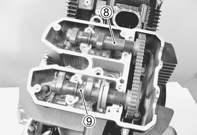
- Remove the intake camshaft 8.
- Remove the exhaust camshaft 9.
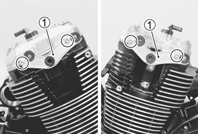
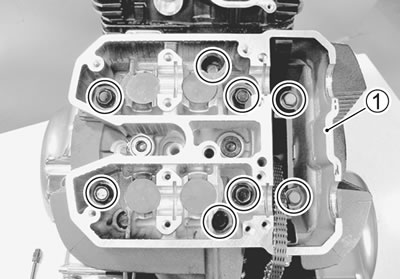
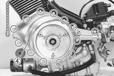
Rear cylinder head
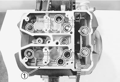
- Remove the cylinder head bolts and washers.
Note: Loosen the cylinder head bolts little by little diagonally with the smaller sizes first.
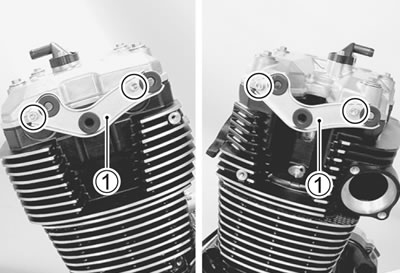
- Remove the cylinder head 1.
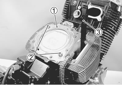
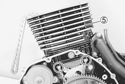
Rear cylinder
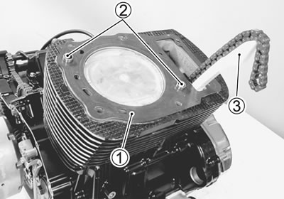
- Remove the cylinder head gasket 1, dowel pins 2 and cam chain guide No. 2 3.
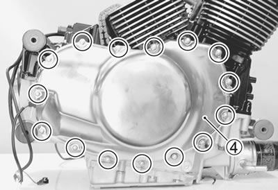
- Remove the clutch cover 4.
- Remove the dowel pins and gasket
- Remove the cylinder nuts.
- Remove the cylinder 5.
Note: Firmly grip the cylinder at both ends, and lift it straight up. If the cylinder does not come off, lightly tap on the finless portions of the cylinder with a plastic mallet to make the gasketed joint loose.
- Remove the cylinder gasket and dowel pins.
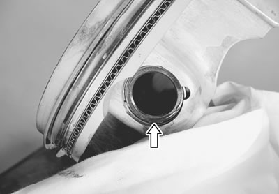
Rear piston
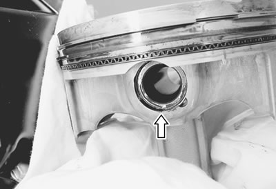
- Place a clean rag over the cylinder base so as not to drop the piston pin circlip into the crankcase.
- Remove the piston pin circlip.
- Remove the piston pin and piston.
Note: Scribe the cylinder number on the head of the piston.
Front cylinder head cover
- Remove the right and left head cover brackets 1.
- Remove the front cylinder head cover 2 and its gasket.
Front camshaft
- Turn the crankshaft to bring the "F I T" line mark on generator rotor to the index mark of the valve inspection hole and also to bring the cams to the position as shown.
Note: At the above condition, the front cylinder is at TDC on expansion stroke and also the engraved lines А on the camshafts are parallel with the mating surface of the cylinder head cover.
- Remove the cam chain tension adjuster cap bolt 3, washer and spring.
- Remove the front cam chain tension adjuster No. 2 4 and gasket.
- Remove the cam chain guide No. 3 5.
- Remove the camshaft journal holder 6.
- Remove the dowel pins.
Caution: Be sure to loosen the camshaft journal holder bolts evenly by shifting the wrench in the descending order of numbers.
- Remove the intake camshaft 7.
- Remove the exhaust camshaft 8.
Front cylinder head
- Remove the cylinder head bolts and washers.
Note: Loosen the cylinder head bolts little by little diagonally with the smaller sizes first.
- Remove the cylinder head 1.
Front cylinder
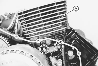
- Remove the cylinder head gasket 1, dowel pins 2 and cam chain guide No. 2 3.
- Remove the generator cover 4.
- Remove the dowel pins and gasket.
- Remove the cylinder nuts.
- Remove the cylinder 5.
Note: Firmly grip the cylinder at both ends, and lift it straight up. If the cylinder does not come off, lightly tap on the finless portions of the cylinder with a plastic mallet to make the gasketed joint loose.
- Remove the cylinder gasket and dowel pins.
Front piston
- Place a clean rag over the cylinder base so as not to drop the piston pin circlip into the crankcase.
- Remove the piston pin circlip.
- Remove the piston pin and piston.
Note: Scribe the cylinder number on the head of the piston.
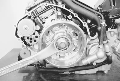
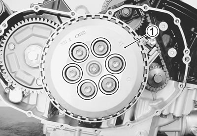
Clutch
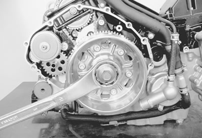
- Hold the generator rotor.
- Remove the clutch spring set bolts and springs.
Note: Loosen the clutch spring set bolts little by little and diagonally.
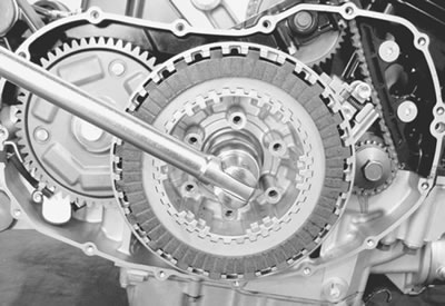
- Remove the pressure plate 1.
- Remove the clutch push piece 2, thrust washer 3 and the bearing 4.
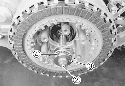
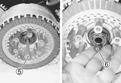
- Remove the clutch push rod 5 and clutch push rod release ball 6.
Note: If it is difficult to pull out the push rod 5 and ball 6, use a long-bar.
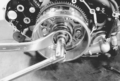
- Unlock the clutch sleeve hub nut.
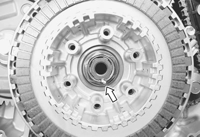
- Hold the generator rotor with a 41 mm offset wrench.
- Remove the clutch sleeve hub nut.
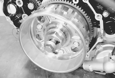
- Remove the spring washer 7, clutch drive plates 8 and driven plates 9 with the clutch sleeve hub 10.
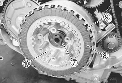
- Remove the thrust washer 11.
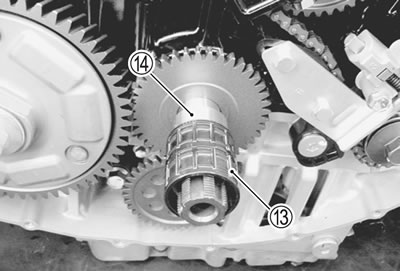
- Remove the primary driven gear assembly 12.
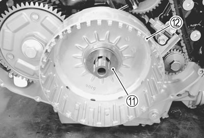
- Remove the needle roller bearing 13 and spacer 14.
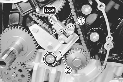
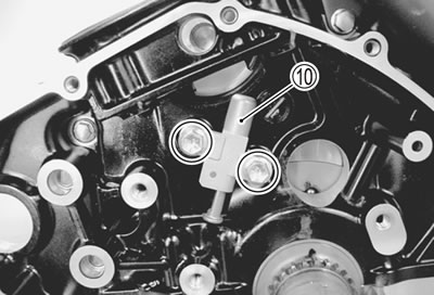
Rear cam chain tension adjuster
- Unlock the ratchet 1 and insert the special tool.
09917-62430: Chain tensioner lock tool
- Remove the rear cam chain tensioner No. 1 assy 2.
- Remove the cam chain guide No. 1 3 and rear cam chain tension adjuster No. 1 4.
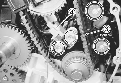
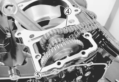
Rear cam chain idler sprocket
- Remove the idler shaft 1.
- Disengage the cam chain No. 1 2 from the rear cam chain idler sprocket 3.
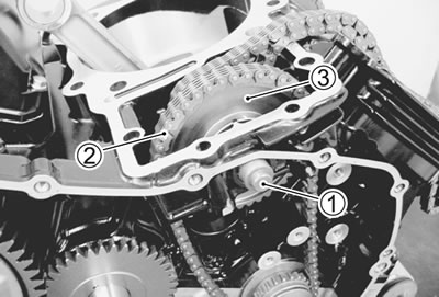
- Remove the cam chain No. 2 4, rear cam chain idler sprocket 5 and cam chain No. 1.
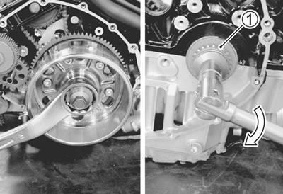
Rear cam chain drive sprocket
- Hold the generator rotor and remove the rear cam chain drive sprocket bolt.
Caution: This bolt has left-hand thread.
- Remove the rear cam chain drive sprocket 1.
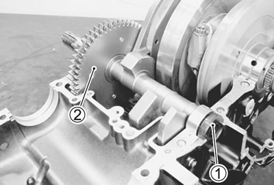
Starter torque limiter/starter idle gear
- Remove the washer 1, starter torque limiter 2 and washer.
- Remove the shaft 3 and starter idle gear 4.
- Remove the bushings 5 from the crankcase and generator.
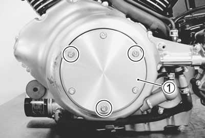
Generator
- Loosen the generator rotor bolt.
Note: When loosen the rotor bolt, do not remove it. The rotor bolt is used in conjunction with the rotor remover when removing the rotor.
- Remove the generator rotor assembly with the special tool.
09930-30721: Rotor remover
- Remove the key 1.
Front cam chain idler sprocket
- Loosen the front cam chain tensioner No. 1 mounting bolt 1 and remove the cam chain guide No. 1 2.
- Remove the idler shaft 3.
- Disengage the cam chain No. 1 4 from the front cam chain idler sprocket 5.
- Remove the cam chain tensioner No. 1 6.
- Remove the cam chain No. 2 7, front cam chain idler sprocket 8 and cam chain No. 1 9.
- Remove the front cam chain tension adjuster No. 1 10.
Secondary driven gear
- Remove the secondary driven gear assembly 1 and shims.
Secondary driven gear inspection (4-6).
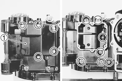
Gearshift
- Remove the gearshift cover 1.
- Remove the gasket and dowel pins.
- Draw out the gearshift shaft assembly 2.
- Remove the gearshift cam plate 3.
- Remove the gearshift cam stopper 4.
Secondary drive gear
- Shift the gear position to 1st or 2nd.
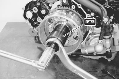
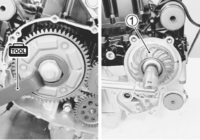
- Hold the primary driven gear with the special tool.
09930-44541: Rotor holder
- Remove the secondary drive gear bolt.
- Secondary drive gear 1 removal.
Secondary drive gear servicing (4-10).
Primary driven gear
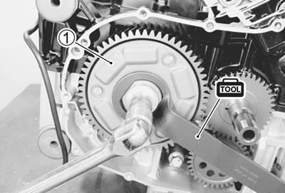
- Hold the primary driven gear with the special tool and remove the primary driven gear bolt.
09930-44541: Rotor holder
- Remove the primary driven gear 1.
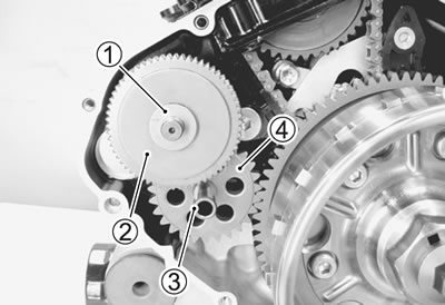
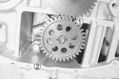
Oil pump driven gear and drive gear
- Remove the snap ring 1.
- Remove the oil pump driven gear 2.
Note: Do not drop the snap ring 1 into the crankcase.
- Remove the pin 3 and washer 4.
Note: Do not drop the pin 3 and washer 4 into the crankcase.
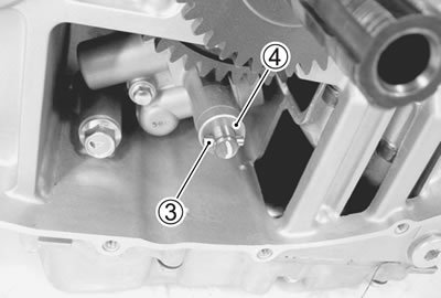
- Remove the oil pump drive gear 5 and pin 6.
Gear position switch
- Remove the gear position switch 1.
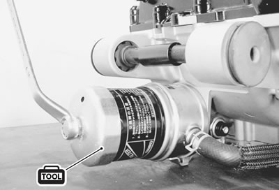
Oil filter
- Remove the oil filter with the special tool.
09915-40610: Oil filter wrench
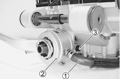
Oil cooler/oil pressure switch
- Disconnect the water hose 1.
- Remove the oil cooler 2 by removing the union bolt.
- Remove the oil pressure switch 3.
Water pump
- Disconnect the water hose 1.
- Remove the water inlet pipe 2, water bypass pipe 3 and water pump 4.
Water pump servicing (8-13).
Oil pan
- Remove the oil pan 1 and stay 2.
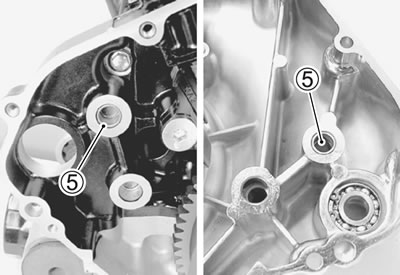
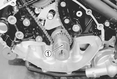
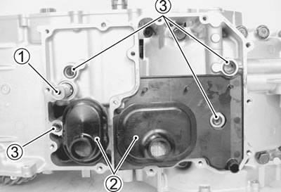
Oil pressure regulator
- Remove the oil pressure regulator 1.
Oil strainer
- Remove the oil strainers 2 and O-rings 3.
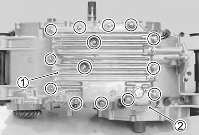
Upper crankcase
- Remove the breather cover 1.
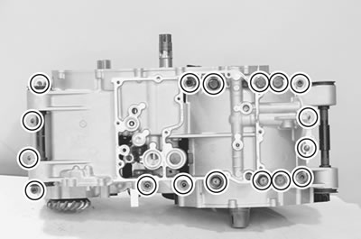
- Remove the upper crankcase bolts.
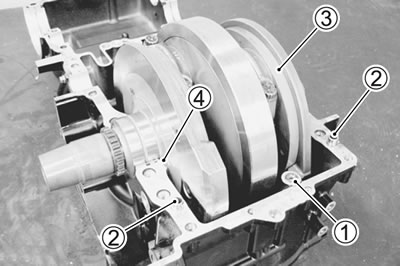
Lower crankcase
- Remove the lower crankcase bolts.
- Make sure that all of the bolts are removed. Then, tap the sides of the lower crankcase using a plastic mallet to separate the upper and lower crankcase halves and then lift the lower crankcase off of the upper crankcase.
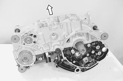
Note:
- The crankshaft and transmission components should remain in the upper crankcase half.
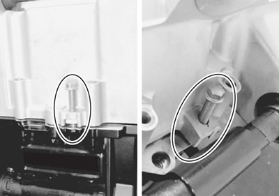
- If it is difficult to separate the crankcase halves, set the proper bolts and nuts to the crankcase by separating the upper and lower crankcase halves, as shown in the illustration.
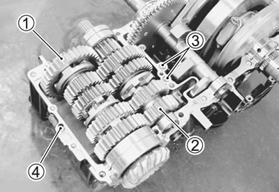
Transmission
- Remove the driveshaft assembly 1 and countershaft assembly 2.
- Remove the O-rings 3 and dowel pin 4.
Balancer shaft
- Remove the oil seal 1 and balancer shaft 2.
Crankshaft
- Remove the O-ring 1 and dowel pins 2.
- Remove the crankshaft 3 and thrust bearing 4.