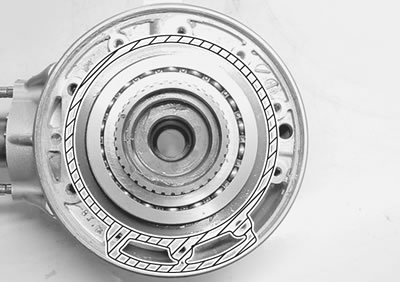
Construction
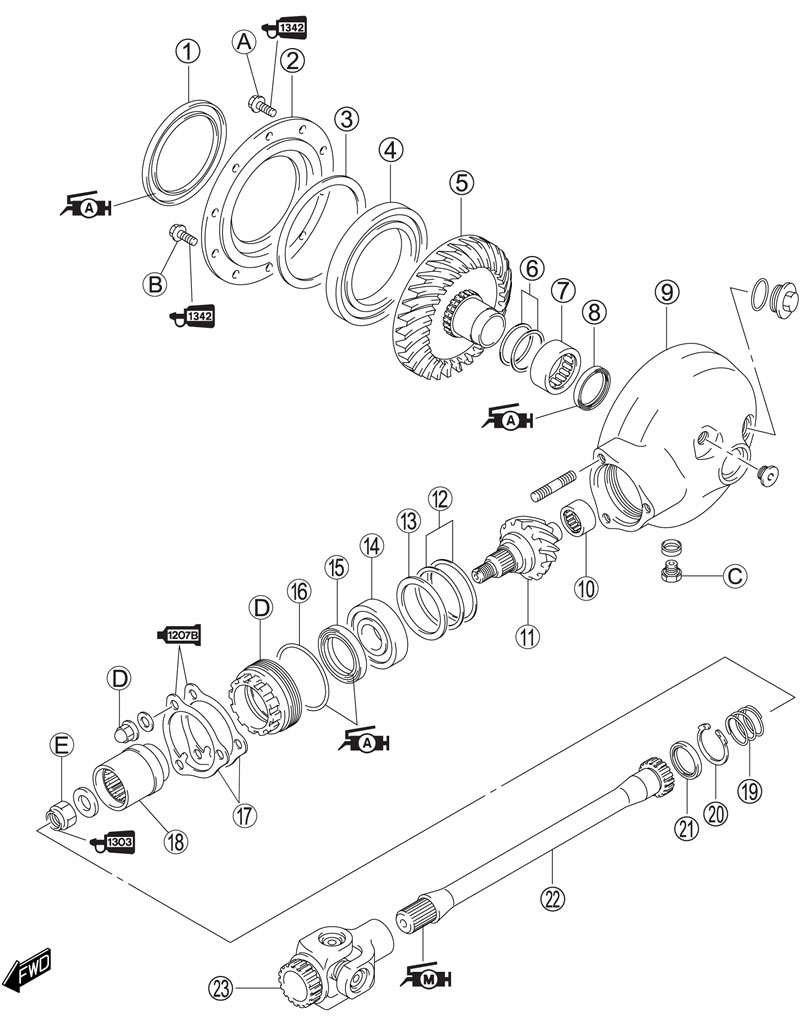
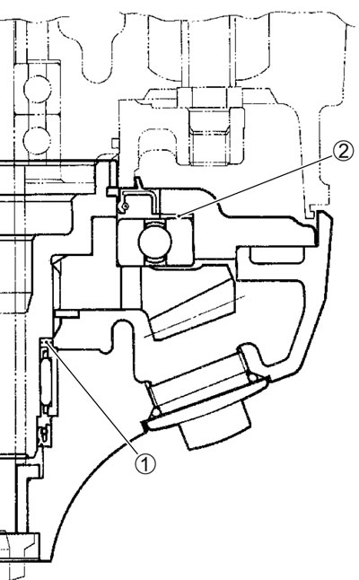
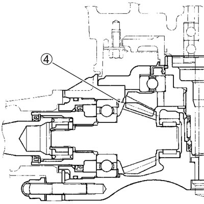
1. Oil seal; 2. Final gear bearing case; 3. Shims; 4. Final driven gear bearing; 5. Final driven bevel gear; 6. Shims; 7. Final driven gear bearing; 8. Oil seal; 9. Final gear case; 10. Final drive gear bearing; 11. Final drive bavel gear; 12. Shims; 13. Washer; 14. Final drive bevel gear bearing; 15. Oil seal; 16. O-ring; 17. Stopper plate; 18. Final drive gear coupling; 19. Spring; 20. Snap ring; 21. Oil seal; 22. Propeller shaft; 23. Universal joint; А. Final gear case bolt (M8); В. Final gear case bolt (M10); С. Oil drain plug; D. Final gear case nut; Е. Final driven gear coupling nut
| ITEM | Nm | kgf·m | lb·ft |
| А | 23 | 2.3 | 16.5 |
| В | 50 | 5.0 | 36.0 |
| С | 23 | 2.3 | 16.5 |
| ITEM | Nm | kgf·m | lb·ft |
| D | 40 | 4.0 | 29.0 |
| Е | 100 | 10.0 | 72.5 |
Standard clearance А: 1.00 mm (0.039 in)
Shim 1 size table
| Part number | Thickness |
| 27445-24A01-030 | 0.30 mm (0.012 in) |
| 27445-24A01-035 | 0.35 mm (0.014 in) |
| 27445-24A01-040 | 0.40 mm (0.016 in) |
| 27445-24A01-050 | 0.50 mm (0.020 in) |
| 27445-24A01-060 | 0.60 mm (0.024 in) |
- The shims 1 are available as a set (27445-24810)
- Standard clearance В: 2.8 mm (0.110 in)
Shim 2 size table
| Part number | Shim thickness |
| 09181-40011 | 0.95 mm (0.026 in) |
| 09181-40013 | 1.05 mm (0.041 in) |
| 09181-40014 | 1.10 mm (0.043 in) |
| 09181-40176 | 1.20 mm (0.047 in) |
| 09181-40182 | 1.40 mm (0.055 in) |
| 09181-40212 | 1.50 mm (0.059 in) |
| 27326-48G00-125 | 1.25 mm (0.049 in) |
| 27326-48G00-135 | 1.35 mm (0.053 in) |
| 27326-48G00-145 | 1.45 mm (0.057 in) |
- The shims 2 are available as a set (27326-48810).
- Shim 3 - Gear case cover clearance: 0.1 mm (0.004 in)
Shim 3 size table
| Part number | Thickness |
| 27327-38B00-035 | 0.35 mm (0.014 in) |
| 27327-38B00-040 | 0.40 mm (0.016 in) |
| 27327-38B00-050 | 0.50 mm (0.020 in) |
| 27327-38B00-060 | 0.60 mm (0.024 in) |
The shims 3 are available as a set (27327-38810).
Final gear case removal
After draining final gear oil, the following components must be removed in the described order before removing the final gear case.
- Drain final gear oil. (2-19)
- Remove the rear wheel. (9-34)
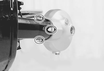
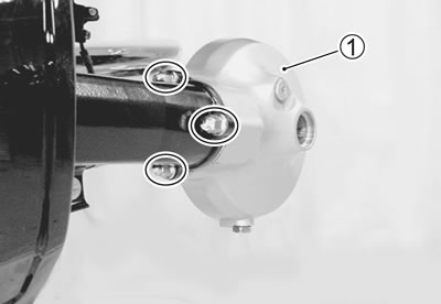
- Remove the final gear case nut, spring washer and final gear case 1.
Final gear case disassembly
- Remove the plate 1.
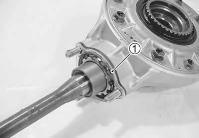
- Remove the dust seal 2.
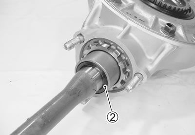
- Remove the snap ring 3.
- 09900-06108: Snap ring pliers
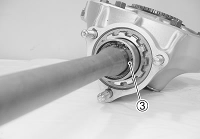
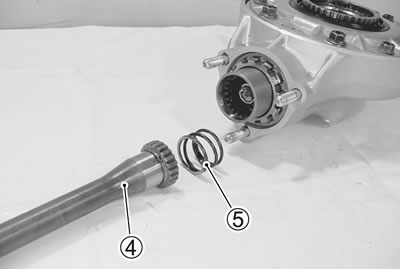
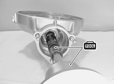
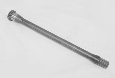
- Remove the propeller shaft 4 and spring 5.
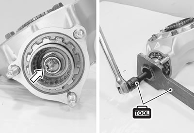
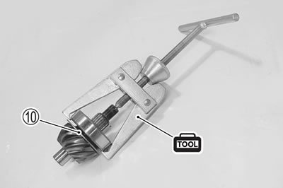
- Using a chisel, unlock the nut.
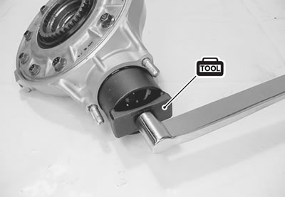
- Remove the final drive gear coupling nut with the special tool.
- 09924-62430: 22 mm Long socket
- 09924-64510: Final drive gear coupling holder
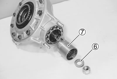
- Remove the washer 6 and the final drive gear coupling 7.
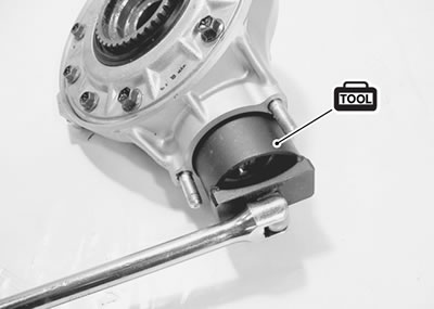
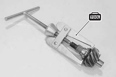
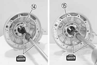
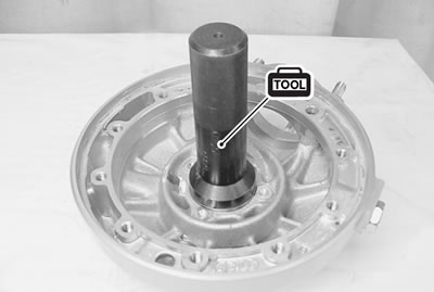
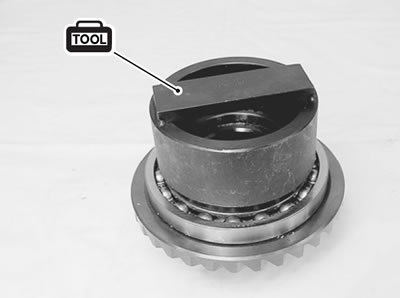
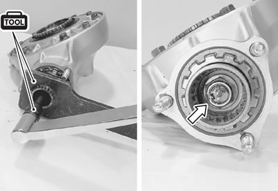
- Remove the bearing stopper with the special tool.
- 09924-62410: Final drive gear bearing holder wrench
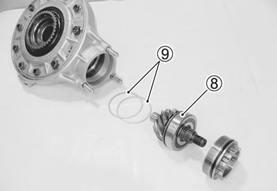
- Remove the final drive bevel gear with bearing 8 and shims 9.
- Remove the bearing with the inner race from the final drive bevel gear with the special tool.
- 09913-60910: Bearing puller
Caution: The removed bearing must be replaced with a new one.
Note: If no abnormal noise, the bearing removal is not necessary.
- Remove the washer 10.
- Remove the inner race with the special tool.
- 09913-60910: Bearing puller
Caution: When replacing the drive bevel gear, replace the driven bevel gear also, as they must be replaced together.
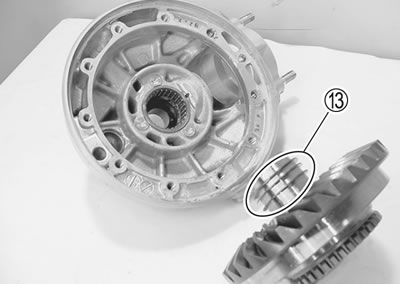
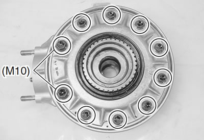
- Remove the final gear bearing case bolts.
- Remove the final gear bearing case from the final gear case, by using two 5 mm screws.
- Remove the shim 11 and final driven bevel gear 12.
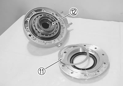
- Remove the shims 13.
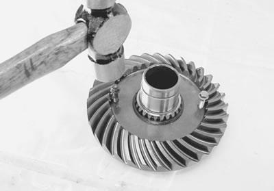
- Using two bolts or suitable bars, remove the final driven bevel gear bearing from the bevel gear.
Note: If no abnormal noise the bearing removal is not necessary.
Caution: The removed bearing must be replaced with a new one.
- Remove the oil seal with the special tool.
- 09913-50121: Oil seal remover
Caution: The removed oil seal must be replaced with a new one.
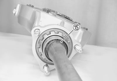
- Remove the final driven gear bearing 14 and oil seal 15 with the special tools.
- 09941-64511: Bearing remover
- 09930-30104: Sliding shaft
Caution: The removed bearing and oil seal must be replaced with new ones.
- Remove the final drive gear bearing with the special tools.
- 09923-74511: Bearing remover
- 09930-30104: Sliding shaft
Caution: The removed bearing must be replaced with a new one.
Note: If no abnormal noise, the bearing removal is not necessary.
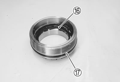
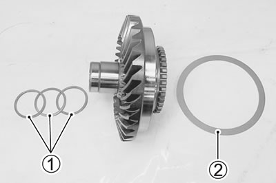
- Remove the oil seal 16 and O-ring 17 from the bearing stopper.
Caution: The removed oil seal and O-ring must be replaced with new ones.
Inspection
Inspect the removed parts for the following abnormalities.
- Drive and driven bevel gear damage or wear
- Improper tooth contact
- Abnormal noise of bearings
- Bearing damage or wear
- Oil seal damage or wear
- Propeller shaft spline damage or wear
- Spring for damage or fatigue
Final gear shims adjustment
Final gear bearing case shim clearance
- Install the final driven gear, shims (1 and 2) and final gear bearing case to the final gear case.
- Tighten the final gear case bolts to the specified torque.
Final gear case bolt:
- (M8): 23 Nm (2.3 kgf·m, 16.5 lb·ft)
- (M10): 50 Nm (5.0 kgf·m, 36.0 lb·ft)
Note: It is not necessary to apply SUZUKI BOND "1207B" and THREAD LOCK to the matching surface and bolts at this stage.
- Measure the clearance between the shims and bearing. If it is not within the specification, the shims must be changed.
- Standard: Final gear case shim clearance
- Standard: 0.1 mm (0.04 in)
Shims 2 specifications
| Part number | Shim thickness |
| 27327-38B00-035 | 0.35 mm (0.014 in) |
| 27327-38B00-040 | 0.40 mm (0.016 in) |
| 27327-38B00-050 | 0.50 mm (0.020 in) |
| 27327-38B00-060 | 0.60 mm (0.024 in) |
Note: The shims 2 are available as a set (27327-38810).
Backlash
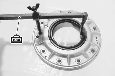
- After assembling the final gear case (4-24), measure the final bevel gear backlash as follows.
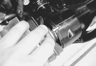
- Install the backlash measuring tool on the drive bevel gear coupling, and set-up a dial gauge as shown in photo.
- 09924-34510: Backlash measuring tool (27 - 50 mm)
- 09900-20607: Dial gauge (1/100 mm, 10 mm)
- 09900-20701: Magnetic stand
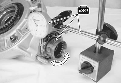
- Adjust the dial gauge so that it touches the backlash measuring tool arm at the mark; hold the final driven bevel gear securely, and turn the final drive bevel gear coupling slightly in each direction, reading the total backlash on the dial gauge.
Final bevel gear backlash: Standard: 0.08 - 0.16 mm (0.003 - 0.006 in)
If the backlash is not within the specification, adjust the shim thickness as follows:
- Remove shims from final gear bearing case and final gear case, and measure total thickness.
- In order not to change the clearance between final driven bevel gear and bearing, the total thickness of the shims installed after a change is made must equal the original total thickness of shims.
If backlash is too large:
- a) Install a thinner shim pack 1 between final driven bevel gear and final gear case.
- b) Increase thickness of shims 2 between final driven bevel gear bearing and bearing case by an amount equal to decrease above.
If backlash is too small:
- a) Install a thicker shim pack 1 between final driven bevel gear and final gear case.
- b) Decrease thickness of shims 2 between final driven gear bearing and bearing case by an amount equal to increase above.
Shims 1 specifications
| Part number | Shim thickness |
| 09181-40011 | 0.95 mm (0.026 in) |
| 09181-40013 | 1.05 mm (0.041 in) |
| 09181-40014 | 1.10 mm (0.043 in) |
| 09181-40176 | 1.20 mm (0.047 in) |
| 09181-40182 | 1.40 mm (0.055 in) |
| 09181-40212 | 1.50 mm (0.059 in) |
| 27326-48G00-125 | 1.25 mm (0.049 in) |
| 27326-48G00-135 | 1.35 mm (0.053 in) |
| 27326-48G00-145 | 1.45 mm (0.057 in) |
The shims 1 are available as a set (27326-48810).
Shims 2 specifications
| Part number | Shim thickness |
| 27327-38B00-035 | 0.35 mm (0.014 in) |
| 27327-38B00-040 | 0.40 mm (0.016 in) |
| 27327-38B00-050 | 0.50 mm (0.020 in) |
| 27327-38B00-060 | 0.60 mm (0.024 in) |
The shims 2 are available as a set (27327-38810).
Example:
- Final gear to case shims 1; 1.45 mm + 1.40 mm = 2.85 mm
- Final gear bearing to bearing case shims 2.
- 0.35 mm + 0.60 mm = 0.95 mm
- Original total measurement = 3.80 mm
Backlash too large:
- Final gear to case shims 1; 1.35 mm + 1.45 mm = 2.80 mm
- Final gear bearing to bearing case shims 2.
- 0.60 mm + 0.40 mm = 1.00 mm
- Total thickness = 3.80 mm
Backlash too small:
- Final gear to case shims 1; 1.50 mm + 1.40 mm = 2.90 mm
- Final gear bearing to bearing case shims 2; 0.50 mm + 0.40 mm = 0.90 mm
- Total thickness = 3.80 mm
Tooth contact
- After backlash adjustment is carried out, the tooth contact must be checked.
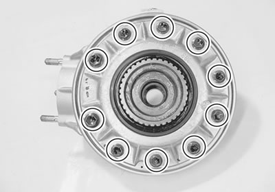
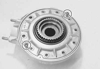
- Remove the bolts from the final gear bearing case, and remove the case with the two 5 mm screws. (4-17) Do not misplace the shims. Remove the final driven bevel gear.
- Clean and de-grease several teeth on the final driven bevel gear. Coat these teeth with machinist's dye or paste, preferably of a light color.
- Re-install the final driven bevel gear with shims in place, positioning the coated teeth so that they are centered on the final drive bevel gear.
- Re-install the final gear bearing case and bolts, and tighten to specification.
Final gear case bolt:
- (M8): 23 Nm (2.3 kgf·m, 16.5 lb·ft)
- (M10): 50 Hm (5.0 kgf·m, 36.0 lb·ft)
Using a socket and handle on the final drive bevel gear coupling nut, rotate the final drive bevel gear several turns in each direction, while loading the final driven bevel gear. This will provide a contact pattern on the coated teeth of the driven bevel gear.
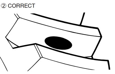
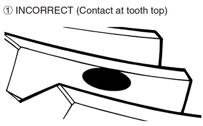
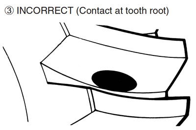
Remove the final gear bearing case and final driven bevel gear, and inspect the coated teeth of the driven bevel gear. The contact patch should be as shown at right:
- If the tooth contact pattern is incorrect, as shown in 1, a thinner shim 4 is needed between the final drive bevel gear bearing and final gear case.
- If the tooth contact pattern is incorrect, as shown in 3, a thicker shim 4 is needed between the final drive bevel gear bearing and final gear case.
- If the tooth contact pattern is incorrect for either reason, the appropriate shim must be installed, and the tooth contact pattern rechecked by repeating the tooth coating procedure above.
Note: If it is necessary to adjust the shim 4 thickness between final drive bevel gear bearing and final gear case, the final gear backlash may change, and should be re-checked according to the procedure outlined under the Backlash Measurement sub-section. Both adjustments may be needed until both backlash and tooth contact are correct.
Shims 4 specification
| Part No. | Shim thickness |
| 27445-24A01-030 | 0.30 mm (0.012 in) |
| 27445-24A01-035 | 0.35 mm (0.014 in) |
| 27445-24A01-040 | 0.40 mm (0.016 in) |
| 27445-24A01-050 | 0.50 mm (0.020 in) |
| 27445-24A01-060 | 0.60 mm (0.024 in) |
The shims 4 are available as a set (27445-24810).
Final gear case reassembly
Assembly
- Reassemble the final gear case in the reverse order of disassembly. Pay attention to the following points.
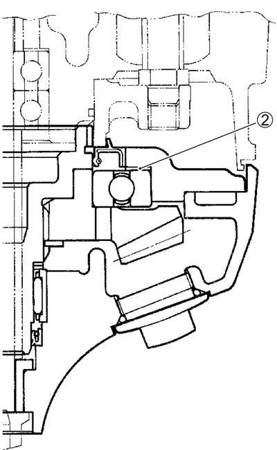
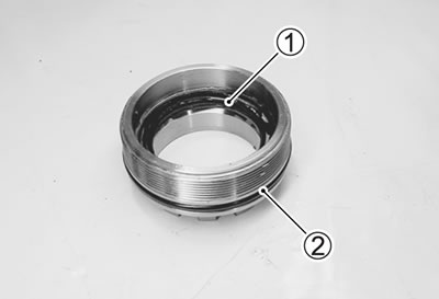
- Install a new oil seal 1 and O-ring 2 to the bearing stopper.
- Install the final drive gear bearing into the final gear case with the special tool.
- 09913-75821: Bearing installer
- Install the oil seal into the final gear case with the special tool.
- 09913-76010: Bearing installer set
Caution:
- Use a new oil seal to prevent oil leakage.
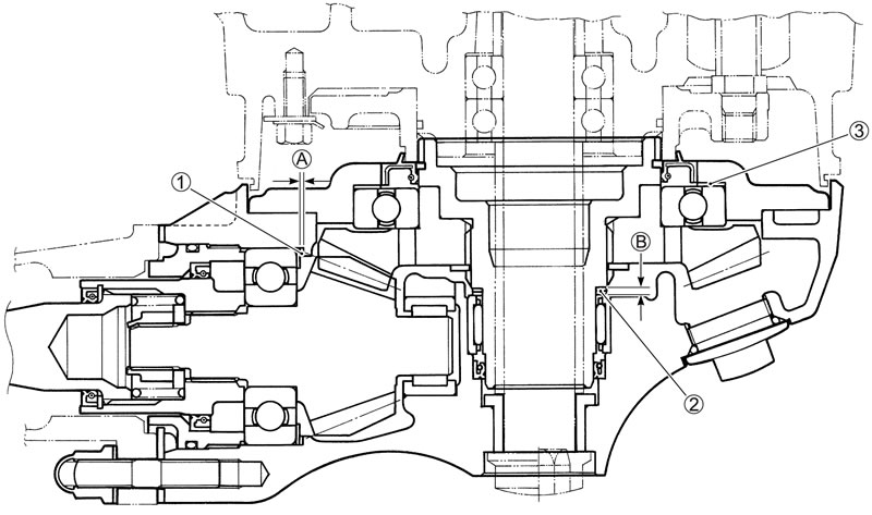
- The lip and spring of the oil seal А should face to the driven bevel gear side.
- Apply SUZUKI SUPER GREASE "A" to the oil seal lip.
- 99000-25010: SUZUKI SUPER GREASE "A" or equivalent
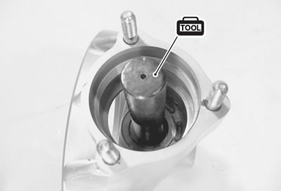
- Install the final driven gear bearing into the final gear case with the special tool.
- 09951-16080: Bearing installer
Note: The stamped mark side of bearing face to the driven bevel gear side.
- Install a new oil seal to the final gear bearing case with the special tool.
- 09951-16310: Final gear case oil seal installer
- Apply SUZUKI SUPER GREASE "A" to the lip of the oil seal.
- 99000-25010: SUZUKI SUPER GREASE "A" or equivalent
- Install the final driven bevel gear bearing to the bevel gear with the special tool.
- 09951-17010: Final driven gear bearing installer
- Install correct shims (3, 4) to the both sides of the final driven bevel gear and install the gear to the final gear case.
Shim adjustment (4-20).
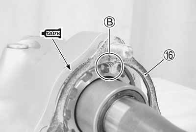
- Apply SUZUKI BOND to the mating surface of the final gear case and final gear bearing case.
Caution: Do not block the breather passage when applying SUZUKI BOND.
- 99000-31140: SUZUKI BOND "1207B" or equivalent
- Apply THREAD LOCK to the final gear case bolts and tighten them to the specified torque.
- 99000-32050: THREAD LOCK "1342" or equivalent
Final gear case bolt:
- (M8): 23 N·m (2.3 kgf·m, 16.5 lb·ft)
- (M10):50 N·m (5.0 kgf·m, 36.0 lb·ft)

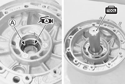
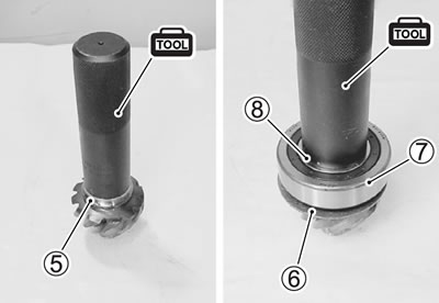
- Install the inner race 5, washer 6, bearing 7 and inner race 8, with the special tool.
- 09913-84510: Bearing installer
Note: When installing the bearing, stamped mark on the bearing must face outside.
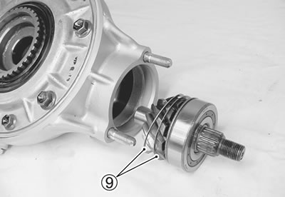
- Install the correct shims 9 to the final drive bevel gear and install the bevel gear to the final gear case.
Shim adjustment (4-23).
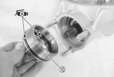
- Apply SUZUKI SUPER GREASE "A" to the O-ring and the lip of oil seal.
- Install the bearing stopper 10.
Caution: Use a new oil seal and O-ring to prevent oil leakage.
- 99000-25010: SUZUKI SUPER GREASE "A" or equivalent
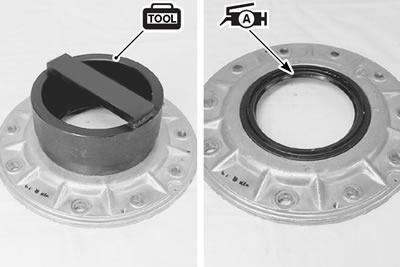
- Tighten the bearing stopper to the specified torque with the special tool.
- 09924-62410: Final drive gear bearing holder wrench
Final drive bevel gear bearing stopper: 110 N·m (11.0 kgf·m, 79.5 lb·ft)
- Install the final drive gear coupling 11 and washer 12.
- Apply a small quantity of the THREAD LOCK SUPER to the final drive gear coupling nut.
- 99000-32030: THREAD LOCK SUPER "1303" or equivalnet
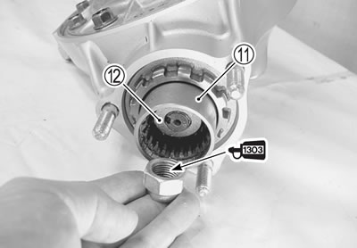
- Tighten the nut to the specified torque with the special tool.
Final drive gear coupling nut: 100 N·m (10.0 kgf·m, 72.5 lb·ft)
- 09924-62430: 22 mm Long socket
- 09924-64510: Final drive gear coupling holder
- Lock the final drive bevel gear coupling nut with a center punch.
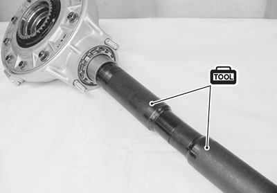
- Apply 5 - 7 cm³ Lithium Base Molybdenum grease (NLGI#2) to the propeller shaft splines and final drive bevel gear coupling.
- Install the spring 13 and propeller shaft 14.
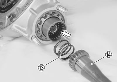
- Install the snap ring 15.
- After installing the propeller shaft with a new snap ring, make sure that the propeller shaft turns smoothly without any hitch or bearing noise.
- 09900-06108: Snap ring pliers
- Install the dust seal with the special tool.
- 09940-51410: Steering bearing installer
- 09925-18011: Bearing installer
- Apply SUZUKI SUPER GREASE "A" to the lip of the dust seal.
Caution: Use a new dust seal to prevent oil leakage.
- 99000-25010: SUZUKI SUPER GREASE "A" or equivalent
- Apply SUZUKI BOND to the mating surface of final gear case.
- 99000-31140: SUZUKI BOND "1207B" or equivalent
- Install the stopper plate 16 to the final gear case.
Caution: When installing the plate, fit the protrusion в of plate to the one of the bearing stopper grooves.
Note: Two kinds of plates are available to lock the stopper at the proper position.
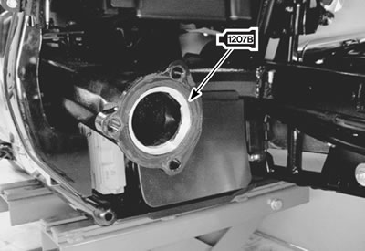
- Apply SUZUKI BOND to the mating surface of swingarm.
- 99000-31140: SUZUKI BOND "1207B" or equivalent
- Apply Lithium Base Molybdenum grease (NLGI#2) to the propeller shaft spline.

Final gear case
Installation
Note: To install the final gear case easily, move the dust boot front and the universal joint turn into the propeller shaft.
- Install the final gear case.
- Tighten the final gear case bolts to the specified torque.
Final gear case nut: 40 N·m (4.0 kgf·m, 29.0 lb·ft)
- Install the rear wheel. (9-39)
- Pour final gear oil. (2-19)