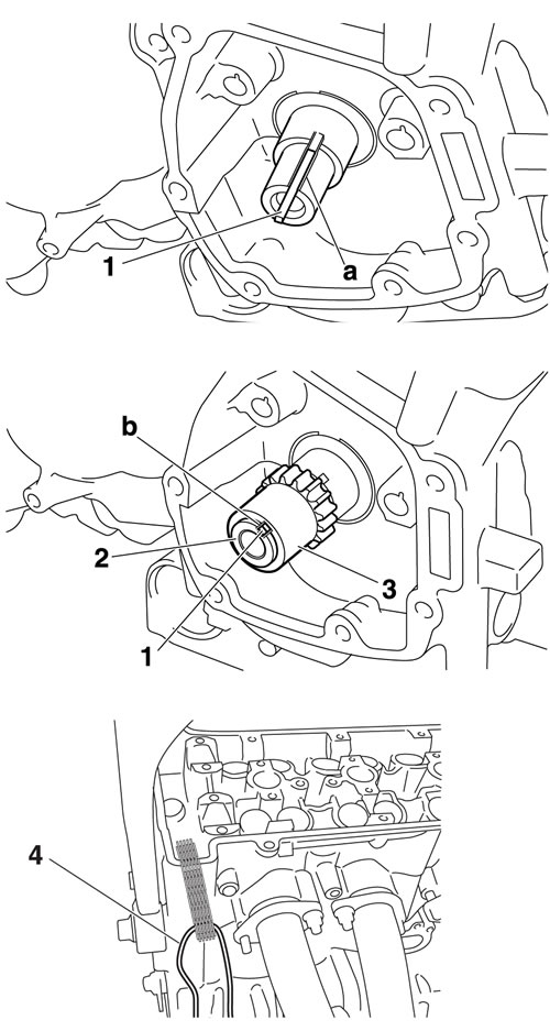
- Woodruff key "1"
- Collar "2"
- Crankshaft sprocket "3"
- Timing chain
- Align the woodruff key to the crankshaft groove "a", collar and crankshaft sprocket groove "b" to the woodruff key and then install.
- To prevent the timing chain from falling into the crankcase, fasten it with a wire "4".
2. Install:
- Pickup rotor
Refer to "Pickup rotor".
Pickup rotor bolt 60 Nm (6.0 m·kgf, 43 ft·lbf).
3. Install:
- Timing chain guide (exhaust side)
- Timing chain guide (intake side)
- Dowel pins
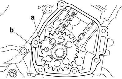
- 4. Align:
- "K" mark "a" on the pickup rotor (with the crankcase mating surface "b").
Notice: When turning the crankshaft with a tool, remove all the spark plugs.
a. Turn the crankshaft clockwise.
b. When position #1 is at BTDC 105°, align the "K" mark "a" with the crankcase mating surface "b".
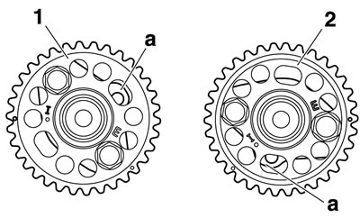
5. Install:
- Intake camshaft sprocket "1"
- Exhaust camshaft sprocket "2"
Camshaft sprocket bolt 24 Nm (2.4 m·kgf, 17 ft·lbf).
Camshaft wrench 90890-04143.
Notice: Be sure to tighten the camshaft sprocket bolts to the specified torque to avoid the possibility of the bolts coming loose and damaging the engine.
2. Install:
- Pickup rotor
Refer to "Pickup rotor".
Pickup rotor bolt
60 Nm (6.0 m·kgf, 43 ft·lbf)
3. Install:
- Timing chain guide (exhaust side)
- Timing chain guide (intake side)
- Dowel pins
4. Align:
- "K" mark "a" on the pickup rotor (with the crankcase mating surface "b").
Notice: When turning the crankshaft with a tool, remove all the spark plugs.
a. Turn the crankshaft clockwise.
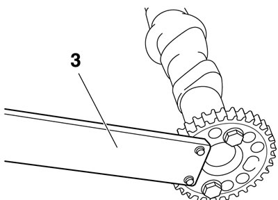
- Install the camshaft projection "a" at the position shown in the illustration.
- Tighten the camshaft sprocket bolt with the camshaft wrench "3".
6. Install:
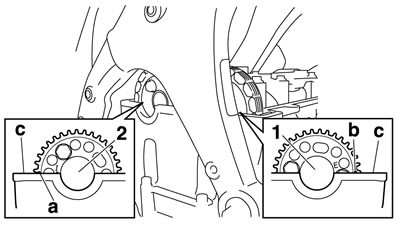
- Exhaust camshaft "1"
- Intake camshafts "2"
- Hang the timing chain on the sprocket from the exhaust camshaft to the intake camshaft, and then put it on the cylinder head.
- The intake camshaft sprocket air intake timing mark "a" and exhaust camshaft sprocket air exhaust timing mark "b" should align with the cylinder head surface "c".
- The timing chain (exhaust side) should be stretched and the timing chain (intake side) should be sagged.
7. Install:
- Dowel pins
- Intake camshaft caps
- Exhaust camshaft caps
- Make sure each camshaft cap is installed in its original place. Refer to the identification marks as follows:
- "I": Intake side camshaft cap mark
- "E": Exhaust side camshaft cap mark
- "IL": Intake left side camshaft cap mark
- "IR": Intake right side camshaft cap mark
- "EL": Exhaust left side camshaft cap mark
- "ER": Exhaust right side camshaft cap mark
- Make sure the arrow mark "a" on each camshaft points towards the right side of the engine.
- When installing the camshaft cap, face the hole with the screw thread "b" on the camshaft cap to the left side of the engine.
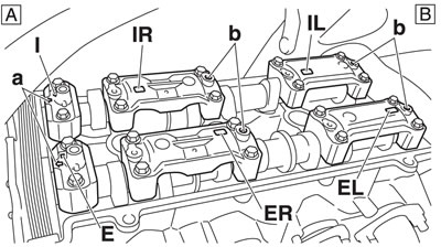
A. Right side; B. Left side
8. Install:
- Camshaft cap bolts
Camshaft cap bolt 10 Nm (1.0 m·kgf, 7.2 ft·lbf).
Notice:
- Lubricate the camshaft cap bolts with the engine oil.
- The camshaft cap bolts must be tightened evenly or damage to the cylinder head, camshaft caps, and camshafts will result.
- Do not turn the crankshaft when installing the camshaft to avoid damage or improper valve timing.
Tighten the camshaft cap bolts in stages and in a crisscross pattern, working from the inner caps out.
9. Install:
- Timing chain tensioner
a. Using a hand press, push and insert timing chain tensioner rod "1" into the timing chain tensioner housing.
Push the timing chain tensioner rod in direction "a", and turn the timing chain tensioner body "2" in direction "b" until it stops.
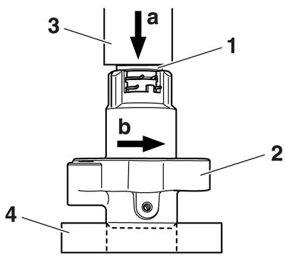
3. Hand press; 4. Bearing
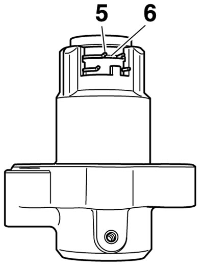
b. Keep pressing the timing chain tensioner rod, mount clip "5" into groove "6", and lock the timing chain tensioner rod.
c. In the status of step "b", install the rod assembly in the cylinder block.
Always use a new gasket.
Timing chain tensioner bolt 10 Nm (1.0 m·kgf, 7.2 ft·lbf).
d. Unlock the timing chain tensioner by turning the crankshaft counterclockwise, and tension the timing chain.
10. Turn:
- Crankshaft (several turns clockwise)
Notice: When turning the crankshaft with a tool, remove all the spark plugs.
11. Check:
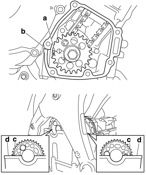
- "K" mark "a"
- Make sure the "K" mark on the pickup rotor is aligned with the crankcase mating surface "b".
- Camshaft sprocket timing mark "c". Make sure the punch mark "c" on the camshaft sprocket is aligned with the cylinder head mating surface "d". Out of alignment → Adjust.
Refer to the installation steps above.
12. Measure:
- Valve clearance
Out of specification → Adjust.
Refer to "Adjusting the valve clearance".
13. Install:
- Pickup coil rotor cover 2
Refer to "Pickup rotor".
14. Install:
- Cylinder head cover gasket New
- Cylinder head cover
- Cylinder head cover bolt 10 Nm (1.0 m·kgf, 7.2 ft·lbf).
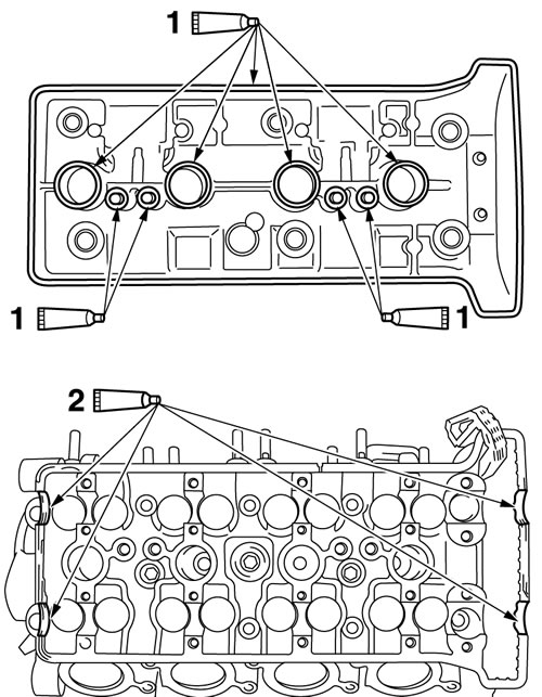
- Apply bond TB1541C® "1" onto the mating surfaces of the cylinder head cover and cylinder head cover gasket.
- Apply bond Yamaha bond No.1215 (Three bond No.1215® "2" onto the mating surfaces of the cylinder head cover gasket and cylinder head.
- Tighten the cylinder head cover bolts stages and in a crisscross pattern.
Yamaha bond No.1215 (Three Bond No.1215®) 90890-85505.
