
Warning! Before starting work, ensure the motorcycle is stabilised and adequately supported. This will help prevent it from falling and causing injury to the operator or damage to the motorcycle.
Removal
Note: Either camshaft can be removed from the cylinder head without complete removal of the cam chain. However, the cam chain must first be detached from the camshafts.
1. Remove the cam cover (see page 3.5).
Note: Turn the engine until the maximum number of cam lobes are facing away from the valves. This will prevent the cams from springing around when the cam chain tensioner is removed.
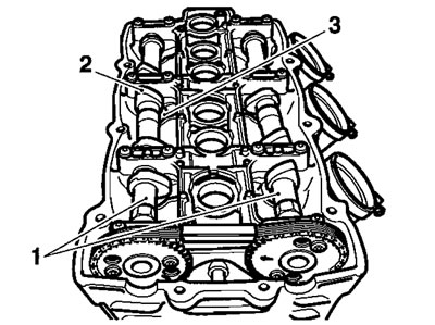
1. Camshafts; 2. Lobes; 3. Valves
2. Remove the cam chain tensioner (see page 3.6).
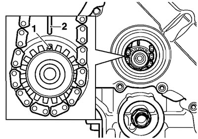
3. Remove the cam chain top pad.
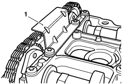
1. Top pad
Caution! To avoid damage to the cam ladder, always ensure as many cam lobes as possible are facing away from the valves. This will reduce stress on the cam ladder during removal. Damage to the cam ladder will result in replacement of the complete head.
4. Progressively and evenly release the remaining cam ladder fixings, half a turn each, until the upward pressure on the bolt heads has been released. Always start from the centre of the engine.

1. Cam ladder; 2. Cam ladder fixings (2 of 16)
Caution! Failure to release the cam ladder fixings progressively and evenly may result in damage to the cam ladder, the camshafts or the cylinder head itself. A damaged cam ladder cannot be replaced as an individual item. It can only be obtained as part of a new cylinder head.
5. Once all the upward force on the cam ladder has been progressively released, collect all the bolts and remove the ladder.
6. Secure the cam chain to prevent it from falling into the front of the engine.
Note: The sound suppression bolt will prevent the cam chain from falling completely away from the head.
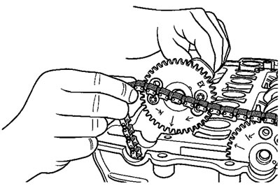
7. Lift the cam chain from one of the camshafts to allow removal of the shaft from the cylinder head.
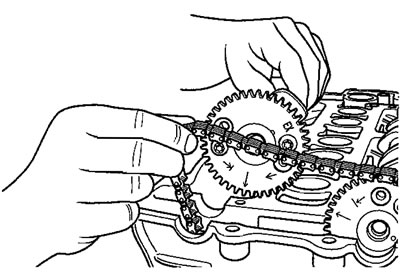
1. Removing a camshaft; 8. Repeat for the second camshaft.
Camshaft identification
The inlet camshaft can be identified by a groove on a machined surface in its centre. The same surface on the exhaust cam is plain.

1. Inlet cam (grooved); 2. Exhaust cam (plain)
Cam sprocket orientation
The same drive sprocket is used for both inlet and exhaust cams.
To attach the sprocket in the correct relationship to the cams, two pairs of offset bolt holes are used, with inlet and exhaust bolt holes being clearly marked ("IN" for inlet and "EX" for exhaust). The holes will also prevent the sprockets from being fitted 180° out of alignment.

1. Sprocket; 2. IN marking; 3. EX marking
To fit a sprocket to an inlet cam, position the sprocket to the cam and align the hole marked «IN» with one of the threaded holes in the camshaft. If both bolt-holes in the cam line up correctly with the holes in the sprocket, the sprocket is in the correct place. If the holes do not line up, then the sprocket should be rotated by a half-turn.

Inspection
1. Inspect the sprockets for damage and worn or broken teeth.
2. Inspect the bearing surfaces in the cylinder head and cam ladder. If wear or damage is found, the cylinder head must be replaced.
3. Inspect the cam chain (see page 3.7).
4. Check camshaft journal to cam ladder clearance using Plastigage (Triumph part number 3880150-T0301) as follows:
Caution! During the flowing procedure, the engine must not be rotated. Damage to valves, pistons and the cylinder head can result from rotating the engine.
a) Position a camshaft to the cylinder head in it's correct location, (inlet cam to inlet valves, exhaust cam to exhaust valves). Ensure that the timing marks on the cam sprocket are positioned as for removal.
b) Release and remove the cam ladder as previously described. Wipe the exposed areas of one of the camshaft journals and the corresponding position on the cam ladder.
c) Apply a thin smear of grease to the wiped camshaft journal and a small quantity of silicone release agent to the corresponding position on the cam ladder.
d) Size a piece of Plastigage to fit across the wiped camshaft journal.
e) Fit the Plastigage to the camshaft journal using the grease to hold it in place.
f) Position the cam ladder to the cylinder head, aligning bearing areas with cam journals. At this stage, it is not necessary to fit the cam chain top pad.
g) Finger-tighten the cam ladder bolts until the under-head areas are in contact with the cam ladder.
h) In the sequence shown below evenly and progressively tighten the cam ladder bolts, approximately half a turn each, until the cam ladder is in full contact with the head.
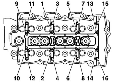
1. Cam ladder tightening sequence
i) In the same sequence, torque each cam ladder bolt to 10 Nm.
j) Release and remove the cam ladder as previously described.
k) Utilising the gauge provided with the Plastigage kit, measure the width of the now compressed Plastigage.

1. Taking a plastigage measurement
5. Calculate the cam journal clearance using the chart provided with the Plastigage kit.
6. If the journal to cam ladder clearance is within the specified tolerances (see table below), remove the cam ladder and clean off all traces of Plastigage, silicone release agent and grease.
| Standard | 0.040-0.091 mm |
| Service limit | 0.13 mm |
7. Check the diameter of the camshaft journals.
| Standard | 22,93-22.96 mm |
8. If any of the journal to cam ladder clearances are outside the specified tolerances, but the camshaft journals are within their specified tolerances, the cylinder head must be replaced.
Installation
1. Correctly identify the inlet and exhaust cams as previously described.
2. Position the camshafts to the two banks of valves ensuring that the inlet cam is located to the inlet valves and the exhaust cam to the exhaust valves.
3. Turn the engine over so that all three pistons are away from TDC (approximately 15° ATDC).
4. Working on one cam at a time, locate the cam chain over the camshaft sprockets.
5. Ease the cam chain away from the sprockets then turn each camshaft until as many lobes as possible are facing away from the valves. Allow the chain to drop back onto the cams.
Caution! To avoid damage to the cam ladder, always ensure as many cam lobes as possible are facing away from the valves. This will reduce stress on the cam ladder during assembly. Damage to the cam ladder will result in replacement of the complete head.
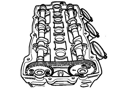
Located camshafts
6. Lubricate the cam bearing areas of the cam ladder with a 50/50 solution of engine oil and molybdenum disulphide grease.
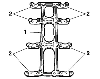
1. Cam ladder; 2. Cam bearing areas
7. Lubricate the threads of the cam ladder bolts with clean engine oil.
8. Position the cam ladder to the cylinder head, aligning bearing areas with cam journals.
9. Finger-tighten the cam ladder bolts until the bolt's under-head areas are in contact with the cam ladder.
10, In the sequence shown below evenly and progressively tighten the cam ladder bolts, approximately half a turn each, until the cam ladder is in full contact with the head.
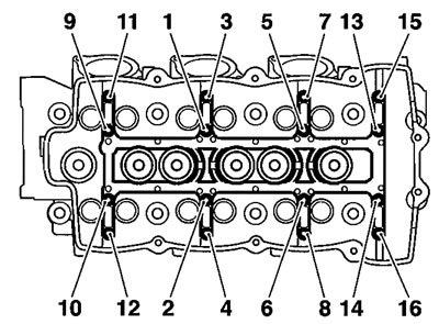
1. Cam ladder tightening sequence
11. In the same sequence, torque each cam ladder bolt to 10 Nm.
12. Fit the cam chain top pad. Tighten the top pad fixings to 10 Nm.
13. Ease the cam chain away from the cams. Rotate the crankshaft clockwise (as viewed from the front), until No. 1 cylinder is at TDC. No. 1 cylinder is at TDC when a «dot» mark on the crank gear is in alignment with the line in the upper crankcase.
1. Crankshaft "dot" mark; 2. Upper crankcase line
Note:
- After placing each cam in the timing position, it will be necessary to have an assistant hold the cams in position until tool T3880202 is fitted.
- Set the exhaust cam first, then the inlet.
14, Ease the cam chain away from the sprockets and position the cams so that the timing marks align as shown below. Allow the cam chain to drop back onto each sprocket after positioning each cam.

1. Inlet timing mark; 2. Exhaust timing mark
15. Fit tool T3880202 to location holes in the cam sprockets as shown in the diagram below. This will hold the cams in the correct timing position and prevent them from turning while the chain tensioner is fitted.

1. Tool T3880202; 2. Cam sprocket holes
16. Refit and assemble the cam chain tensioner plunger, spring and centre nut (see page 3.7).
17. Remove tool T3880202.
18. Turn the engine over at least four times, then check the cam timing again. Reset as necessary
19. Check all valve clearances (see page 3.14). Adjust as necessary to give the correct clearances.
20. Refit the cam cover (see page 3.6).