| PART NO. | SPECIALTY TOOL |
| HD-45314 | Crankshaft rotating wrench |
| HD-45653 | TDC positioning tool |
| HD-45306 | Crankshaft locking pin |
| HD-45491 | Tappet compressing tool |
1. Install TDC POSITIONING TOOL (HD-45653) in front spark plug hole.
Caution! Never insert a foreign object, such as a screwdriver, in the spark plug hole. Engine damage can result.
Caution! DO NOT ROTATE ENGINE CLOCKWISE. This is opposite the normal engine operation. Engine damage may result.
2. Using CRANKSHAFT ROTATING WRENCH (HD-45314) rotate the engine counter-clockwise (direction of operation). Note when exhaust valve is closing (TDC positioning tool will start to extend as valve closes) and engine is approaching TDC.
3. When the TDC reference tool is fully extended, remove plug from timing hole on right side of engine and insert CRANKSHAFT LOCKING PIN (HD-45306).
4. The CRANKSHAFT LOCKING PIN should insert flush with engine case. It may be necessary to gently rock the crankshaft using the CRANKSHAFT ROTATING WRENCH (HD-45314) to lock engine at exact TDC.
5. Remove TDC POSITIONING TOOL (HD-45653) from front spark plug hole.
6. If removed, record shim thickness for reference and install all eight shims in their original location. Use a magnet to position the shim and push into place with finger.
7. Replace tappets in their original locations.
8. See Figure 3-252. Insert rear cylinder cam drive chain down from the rear head. Wrap chain around middle row of triple sprocket teeth with the copper chain links straddling the triple gear timing marks.

Figure 3-252. Copper timing links
9. See Figure 3-253. Lubricate cam journals, lobes, and tappets with Harley-Davidson Motorcycle Oil 20W50. In addition, a thin film of Lubriplate No. 105 Motor Assembly Grease (NAPA Part No. 765-2651) is recommended.
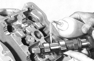
Figure 3-253. Lubricate cam
10. See Figure 3-254. Insert rear exhaust cam into cylinder head and rotate cam sprocket so single copper link (14) straddles the single dot timing mark labeled as EX (13).
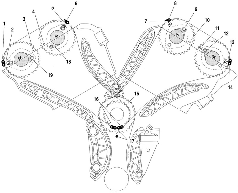
Figure 3-254. Cam Drive Timing Marks (secondary cam chain tensioners are not shown): 1. Front exhaust chain copper link; 2. Front exhaust EX timing dot; 3. Front exhaust alignment mark (single dot and line); 4. Front intake alignment mark (two dots and line); 5. Front intake IN timing dot; 6. Front intake copper link; 7. Rear intake IN timing dot; 8. Rear intake copper link; 9. Rear intake cam lobe position; 10. Rear intake alignment mark (three dots and line); 11. Rear exhaust alignment mark (four dots and line); 12. Rear exhaust cam lobe position; 13. Rear exhaust EX timing dot; 14. Rear exhaust chain copper link; 15. Triple sprocket; 16. Twin cam drive chain copper links; 17. Triple sprocket to crankcases alignment marks; 18. Front intake cam lobe position; 19. Front exhaust cam lobe position
Note: Crankshaft must be at TDC with CRANKSHAFT LOCKING PIN in place.
11. Insert rear intake cam into cylinder head and rotate cam sprocket so single copper link (8) straddles the single dot timing mark labeled IN (7).
12. Verify that the single copper links on the cam drive chain straddle the single dot timing marks and that the three dot timing line (10) on the intake cam and the four dot timing line (11) on the exhaust cam at the cam cover gasket surface are aligned.
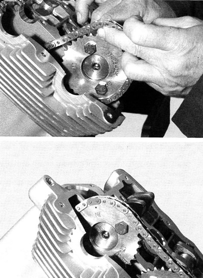
Figure 3-255. Rear cylinder cams
13. See Figure 3-256. Lubricate cam journal caps and fasteners.
14. Cam journal caps are numbered. Install cam journal caps with corresponding number on head, arrow pointing to center of head.
15. Tighten cam journal caps to 9.7 Nm (85 in-lbs).
16. See Figure 3-257. Install rear cylinder cam chain tensioner and tighten to 100 Nm (78 ft-lbs).
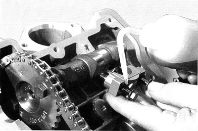
Figure 3-256. Lubricate journal caps and fasteners
Caution! NEVER rotate engine with secondary cam chain tensioner removed. Engine damage and/or loss of correct timing will occur.
17. See Figure 3-28. Install TAPPET COMPRESSING TOOL (HD-45491) on front cylinder.
- a. Loosen 19 mm nut on tappet compressing tool.
- b. Tools are marked intake and exhaust. Position them accordingly.
- c. Use M6x25 fasteners to secure tools to head.
18. Tighten 19 mm nut to compress tappets.
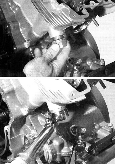
Figure 3-257. Rear cylinder cam chain tensioner
19. See Figure 3-258. Insert front cylinder timing cam drive chain down from the front head. Wrap chain around front row of triple sprocket teeth with the copper chain links straddling the triple gear timing marks.
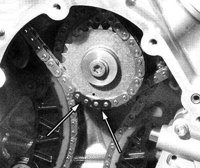
Figure 3-258. Copper links
20. Lubricate cam journals, lobes, and tappets with Harley-Davidson Motorcycle Oil 20W50. In addition, a thin film of Lubriplate No. 105 Motor Assembly Grease (NAPA Part No. 765-2651) is recommended.
21. See Figure 3-254. Insert front exhaust cam into cylinder head and rotate cam sprocket so single copper link (1) straddles the single dot timing mark labeled EX (2).
22. Insert front intake cam into cylinder head and rotate cam sprocket so single copper link (6) straddles the single dot timing mark labeled IN (5).
23. Install and tighten cam journal caps to 9.7 Nm (85 in-lbs).
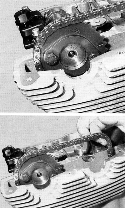
Figure 3-259. Cam chain alignment
24. Verify that the single copper links on the front cylinder cam drive chain straddle the single dot timing marks and that the one dot timing line (3) on the exhaust cam and the two dot timing line (4) on the intake cam at the cam cover gasket surface are aligned.
Note. Compare lobe positions of each cam shaft to Figure 3-254. If timing marks are correct but camshaft lobes are incorrect, the drive sprocket could be installed incorrectly on the camshaft.
25. Remove TAPPET COMPRESSION TOOL.
26. Install front cylinder cam chain tensioner and tighten to 100 Nm (78 ft-lbs).
27. Check valve lash and adjust as necessary. See 1.22 Valve lash.
28. Remove CRANKSHAFT LOCKING PIN (HD-45306).
29. Install the engine timing plug and tighten to 23 Nm (17 ft lbs).
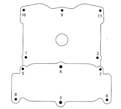
Figure 1-260. Cam cover torque sequence
30. Install cam cover and tighten fasteners to 9.7 Nm (86 in-lbs) in sequence shown. See 1.22 Valve lash.
31. See Figure 3-261. Install starter limiter gear assembly and starter limiter fastener. Tighten fastener to 46 Nm (34 ft-lbs).
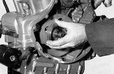
Figure 3-261. Starter limiter gear fastener

Figure 3-262. Install needle roller and cage, gear ball clutch and washer

Figure 3-263. Gear ball clutch retaining ring
32. See Figure 3-264. Install rotor shell and tighten.
- a. Tighten to 82 Nm (60 ft-lbs).
- b. Loosen one full turn.
- c. Tighten to 180 Nm (132 ft-lbs).
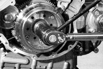
Figure 3-264. Install rotor shell @ 82 Nm (60 ft-lbs)
Note. Check to be certain woodruff key has not slipped out of keyway during assembly.
