Gearbox shafts diagram (Aprilia Shiver 750)
- Main
- Aprilia
- Shiver
- SL 750
- Engine and systems
- Transmission
- Gearbox shafts diagram
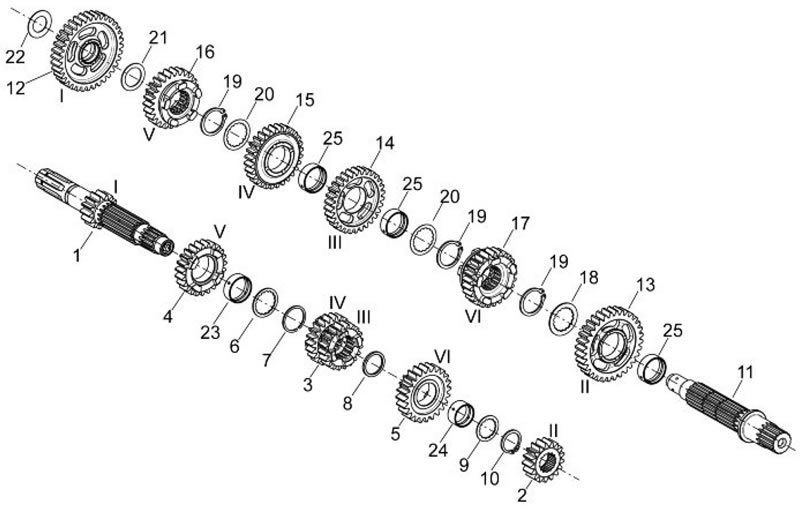
1. Main gear shaft Z=14; 2. 2nd gear on primary Z=17; 3. 3rd - 4th gear on secondary Z=20/22; 4. 5th gear on primary Z=23; 5. 6th gear on primary Z=24; 6. Thrust washer; 7. Circlip; 8. Thrust washer; 9. Thrust washer; 10. Circlip; 11. Transmission shaft; 12. 1st gear on primary Z=36; 13. 2nd gear on secondary Z=32; 14. 3rd gear on secondary Z=30; 15. 4th gear on secondary Z=28; 16. 5th gear on secondary Z=26; 17. 6th gear on secondary Z=25; 18. Thrust washer; 19. Circlip; 20. Thrust washer; 21. Thrust washer; 22. Thrust washer; 23. Floating bushing; 24. Floating bushing; 25. Floating bushing
The material is based on data from the website MotoInstruction.ru
See this article in russian language
This article has been reviewed: Serafim Sazonov
Similar articles about motorcycles of other brands
Removing gearbox shafts BMW R 1150 GS (1999-2004)Gearbox assembly: gearbox shafts Ducati Monster 696 (2007-2014)
Exploded view — input and output shafts Triumph Rocket III (2004-2018)
Wiring and cable routing diagram Yamaha FZ1 Fazer (2006-2015)
Block diagram of the engine lubrication system Suzuki DRZ 250 (1996-2007)
Link to this article in different formats
Comments and feedback from visitors
No comments yet, you will be the first!
- Information for owner
- Introduction to manual
- Control devices
- Operation manual
- Technical characteristics
- Maintenance
- Engine and systems
- Engine repair
- Lubrication system
- Cooling system
- Fuel system
- Transmission
- Running gear and frame
- Frame and hinged elements
- Front suspension and handlebar
- Rear suspension
- Brake system
- Electric equipment
- Equipment and devices
