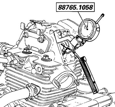
- screw the dial gauge code number 88765.00968 in the spark plug hole of the cylinder to be tested;
- remove the closing cover and apply the tool with protractor code number 88713.0123 to the left cover;
- remove the valve inspection covers and fit the gauge code number 88765.1058 in the fixing hole of the cover just removed (for the sake of convenience, fit one gauge for the exhaust valve and another for the intake valve);
- check that the gauge fork stylus is in the center of the valve axis and that it is resting on the closing adjuster;
- insert the blade of a feeler gauge (A), with the correct thickness, between the upper rocker arm and the opening pin to eliminate any valve play;
- turn the crankshaft with this tool to find the TDC position of the horizontal piston with the valve completely closed. In this condition, the reference on the clutch cover must be aligned with the reference on the timing pulley.
- in this position, zero the dial gauge, the gauge index and the protractor compared to the set values;
- turn the protractor in an anticlockwise direction until the index on the gauge dial starts to move;
- continue rotating until the valve lifts by 1 mm;
- check that the angular displacement is correct (refer to the "Description" section);
- continue rotating the crankshaft in an anticlockwise direction to check the value of the maximum valve lift on the gauge;
- continue rotating to find the final valve closing point;
- then reverse the rotation direction (clockwise) and, using the protractor, raise the valve by 1 mm;
- check that the angular value on the protractor is correct.
 |  |
Proceed in the same way for the other valve and then for the other cylinder.
A tolerance of±3° compared to the set values is permitted for the values measured with this procedure.
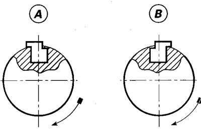
If the accumulation of machining tolerances is so considerable that timing with timing components is unsuccessful, adjust this error with off-center pulley adjustment tabs. Table В lists the off-center values "D" in mm, the corresponding crankshaft out-of-timing values and the relative code number for the special tabs supplied and their punchings.

The diagram shows the correct assembly position of the special tabs for "advance" (A) and "retard" (B) adjustment, in relation to the rotation of the timing shaft.

| off-centre values in mm | shaft out-of-timing | code number | punching |
| 0.15 | 2° | 680 1003 1A | A (1) |
| 0.30 | 4° | 680 1003 1В | В (2) |
| 0.45 | 6° | 680 1003 1C | C (3) |
| 0.60 | 8° | 680 1003 1D | D (4) |
| 0.75 | 10° | 680 1003 1E | E (5) |
Caution! When the timing operations have been completed, the timing belt tension must be at the set value.
