Engine removal and disassembly
| PART NUMBER | TOOL NAME |
| HD-42310-45 | ENGINE SUPPORT CRADLE |
1. Remove engine from chassis. See 3.10 REMOVING ENGINE FROM CHASSIS.
2. Support engine using ENGINE SUPPORT CRADLE (Part No. HD-42310-45).
3. Disassemble top end. See 3.13 TOP END OVERHAUL: DISASSEMBLY.
4. Remove primary cover, clutch assembly, primary chain and engine sprocket. See 5.4 PRIMARY DRIVE AND CLUTCH: XL MODELS or 5.5 PRIMARY DRIVE AND CLUTCH: XR 1200X.
5. Disassemble gearcase. See 3.17 BOTTOM END OVERHAUL: DISASSEMBLY.
6. Remove transmission sprocket.
7. See Figure 5-45. Place transmission in 1st gear. Remove countershaft retaining screw (1).
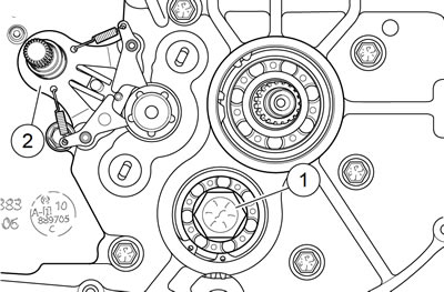
Figure 5-45. Countershaft retaining screw: 1. Countershaft retaining screw; 2. Shifter shaft assembly
8. Place transmission in neutral. See Figure 5-46. Unplug neutral switch connector [131] (2) by pulling connector straight off neutral switch (1). Remove neutral switch and flat washer.
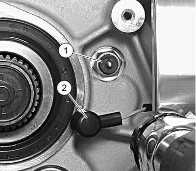
Figure 5-46. Neutral switch and connector: 1. Neutral indicator switch; 2. Neutral switch connector
9. See Figure 5-47. Verify shifter drum detent is visible in neutral switch hole indicating that transmission is in neutral.
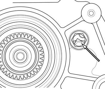
Figure 5-47. Shifter drum neutral detent
10. See Figure 5-48 and Figure 5-49. Compress the ratchet arms (item 2, Figure 5-48) in order to clear the shifter drum, and remove shifter shaft assembly from left crankcase half.
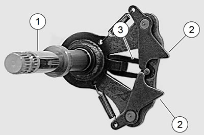
Figure 5-48. Shifter shaft assembly: 1. Shifter shaft; 2. Ratchet arms; 3. Return spring

Figure 5-49. Removing shifter shaft assembly
11. Remove starter. See 6.10 STARTER.
12. See Figure 5-50. With transmission still in neutral, scribe a line on the end of the shifter drum at the 12 o'clock position for later reference.
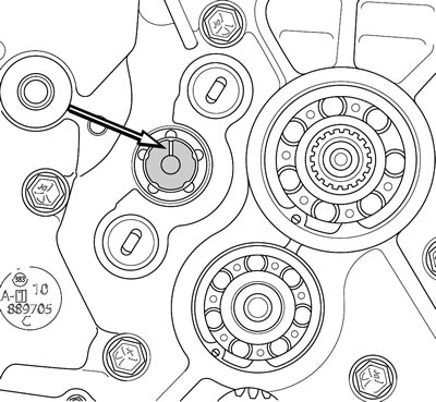
Figure 5-50. Scribed line on shifter drum at 12 o'clock
Note. Crankcase assembly has 17 fasteners: 15 inserted from left side and two inserted from right side. Make certain all fasteners have been removed before attempting to separate crankcase halves.
13. See Figure 5-51. Remove 15 crankcase fasteners (11 long and four short) from left side of crankcase assembly. Remove two fasteners from right side of crankcase assembly.
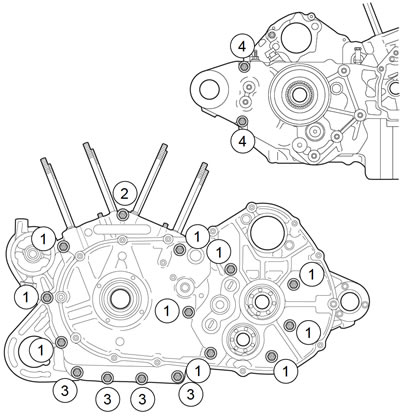
Figure 5-51. Crankcase fasteners: 1. Long fastener: left side; 2. XR 1200X: double-headed long fastener; 3. Short fastener: left side; 4. Long fastener: right side
14. Tap crankcase gently with rawhide mallet to loosen and separate the halves. See Figure 5-52. Remove left crankcase assembly with transmission.
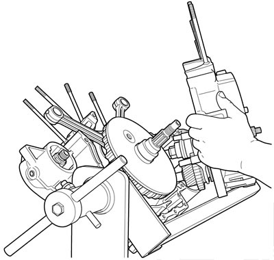
Figure 5-52. Separating crankcase halves
Note. Flywheel assembly slides off left main bearing by hand. No tools are required for this operation.
15. See Figure 5-53. Remove flywheel assembly from right crankcase half.
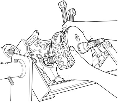
Figure 5-53. Removing flywheel assembly from right crankcase half
16. See Figure 5-54. Remove screw (1), gear detent assembly (2) and detent spring (3) from inside transmission cavity of right crankcase.
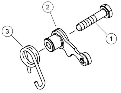
Figure 5-54. Gear detent assembly: 1. Screw; 2. Gear detent assembly; 3. Detent spring
