
Transmission removal from left crankcase
| PART NUMBER | TOOL NAME |
| B-43895-1 | REMOVER |
| B-43985 | TRANSMISSION REMOVAL AND INSTALLATION TOOL |
Note. See Figure 5-55. Shifter design allows for one common part number for both countershaft shifter forks (4, 5). As the transmission runs, each shifter fork develops a certain wear pattern with its mating parts. Install shifter forks in original locations.
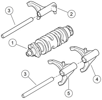
Figure 5-55. Shifter forks, drum and shafts: 1. Shifter drum; 2. Mainshaft shifter fork (4th/5th); 3. Shifter fork shaft; 4. Countershaft shifter fork (1st); 5. Coutnershaft shifter fork (2nd/3rd)
1. See Figure 5-56. Remove shifter fork shafts by inserting a small flat punch in the slots and tapping on the end of each shaft until it falls free.

Figure 5-56. Slots for removing shifter fork shafts
Note. Carefully tap on alternate sides of the shaft using the provided slots.
2. See Figure 5-57. Remove shifter drum (1) and shifter forks (2). Mark each shifter fork as it is removed, so it can be reinstalled in the same location.
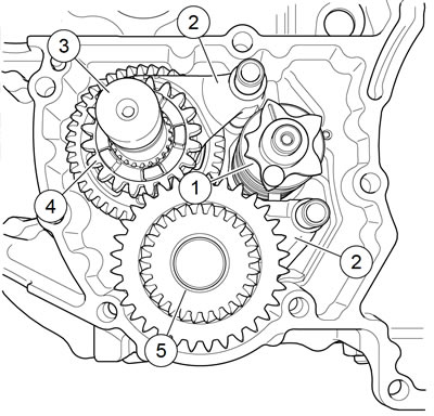
Figure 5-57. Transmission assembly: 1. Shifter drum; 2. Shifter fork (3); 3. Mainshaft; 4. Mainshaft 2nd gear; 5. Countershaft
Warning! Wear safety glasses or goggles when removing or installing retaining rings. Retaining rings can slip from the pliers and could be propelled with enough force to cause serious eye injury.
Note. Use the TRANSMISSION REMOVAL AND INSTALLATION TOOL (Part No. B-43985) to remove the transmission.
3. See Figure 5-58. Remove left crankcase half and transmission assembly (4) from engine stand.
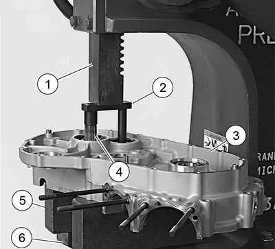
Figure 5-58. Pressing transmission from left crankcase: 1. Press ram; 2. Transmission remover; 3. Crankcase; 4. Transmission assembly (countershaft visible); 5. Parallel support (2); 6. Press bed
- a. Place crankcase half (3) and transmission assembly (4) on arbor press (1) and support transmission assembly on parallel supports (5).
- b. Press transmission assembly using REMOVER (Part No. B-43895-1) (2) to remove transmission from crankcase half.
- c. Remove crankcase from press.
Main shaft/countershaft
Notes:
- Transmission operation creates a specific wear pattern on the parts. Always install parts in their original locations and orientations.
- See Figure 5-59. As each component is removed, place it on a clean surface in the exact order of removal.
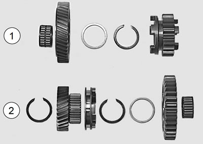
Figure 5-59. Transmission parts identification: 1. Mainshaft; 2. Countershaft
Mainshaft disassembly
| PART NUMBER | TOOL NAME |
| J-5586-A | TRANSMISSION SHAFT RETAINING RING PLIERS |
Notes:
- Mainshaft 2nd and 3rd gears are integral to the shaft.
- Mainshaft 1st gear is directional. Mark gear when removed for correct installation.
- Press transmission assembly out of left crankcase half to service mainshaft and countershaft.
- All thrust washers are one common part number. This transmission requires no shimming.
- Use correct retaining ring pliers and correct tips. Verify that tips are not excessively worn or damaged.
Warning! Wear safety glasses or goggles when removing or installing retaining rings. Retaining rings can slip from the pliers and could be propelled with enough force to cause serious eye injury.
1. See Figure 5-60. Remove 1st gear (1).
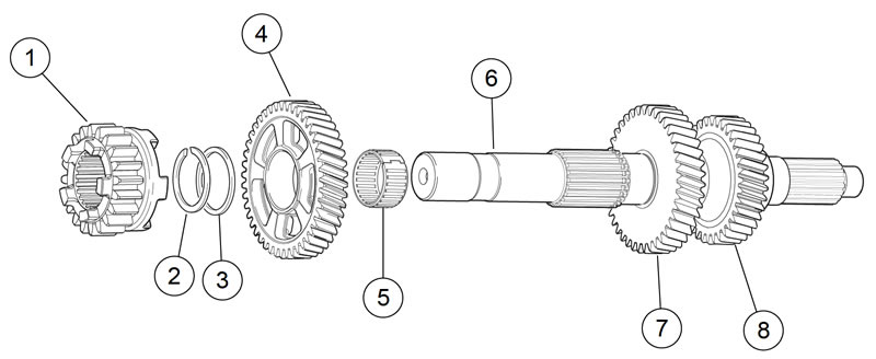
Figure 5-60. Transmission mainshaft assembly once removed from left crankcase/disassembly: 1. Mainshaft 1st gear; 2. Retaining ring; 3. Thrust washer; 4. Mainshaft 4th gear; 5. Split bearing; 6. Mainshaft; 7. Mainshaft 3rd gear (integral to shaft); 8. Mainshaft 2nd gear (integral to shaft)
2. Use TRANSMISSION SHAFT RETAINING RING PLIERS (Part No. J-5586-A) to expand and remove retaining ring (2). Discard retaining ring.
3. Slide thrust washer (3) off end of mainshaft.
4. Remove 4th gear (4) and split bearing (5). Discard bearing.
Cleaning and inspection
Warning! Compressed air can pierce the skin and flying debris from compressed air could cause serious eye injury. Wear safety glasses when working with compressed air. Never use your hand to check for air leaks or to determine air flow rates.
1. Clean all parts in cleaning solvent. Blow dry with compressed air.
2. Check gear teeth for damage. Replace if necessary.
3. Inspect the engaging dogs on the gears. Replace if necessary.
Countershaft disassembly
| PART NUMBER | TOOL NAME |
| J-5586-A | RETAINING RING PLIERS |
Notes:
- Countershaft 5th gear is integral to the shaft.
- Once the transmission assembly has been pressed out of the left crankcase half, the mainshaft and countershaft assemblies can be serviced separately.
- All thrust washers are one common part number. This transmission requires no shimming.
- Use correct retaining ring pliers with correct tips. Verify that tips are not excessively worn or damaged.
Warning! Wear safety glasses or goggles when removing or installing retaining rings. Retaining rings can slip from the pliers and could be propelled with enough force to cause serious eye injury.
1. See Figure 5-61. Remove spacer (19) and 2nd gear (18) from the end of the of the countershaft (2). Remove and discard split bearing (17).
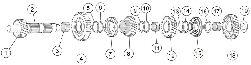
Figure 5-61. Transmission countershaft assembly once removed from left crankcase/disassembly: 1. Countershaft 5th gear (integral to shaft); 2. Countershaft; 3. Split bearing; 4. Countershaft 1st gear; 5. Thrust washer; 6. Retaining ring; 7 Dog ring; 8. Countershaft 4th gear; 9. Retaining ring; 10. Thrust washer; 11. Split bearing; 12. Countershaft 3rd gear; 13. Thrust washer; 14. Retaining ring; 15. Dog ring; 16. Spacer; 17. Split bearing; 18. Countershaft 2nd gear; 19. Spacer
2. Remove spacer (16).
Note. When removing the dog ring (15), it is important to mark the direction of the ring on the shaft as parts establish wear patterns.
3. Remove dog ring (15).
4. Using RETAINING RING PLIERS (Part No. J-5586-A), expand and remove retaining ring (14). Discard retaining ring.
5. Remove thrust washer (13), 3rd gear (12), and split bearing (11). Discard bearing.
6. Remove thrust washer (10).
7. Expand, remove and discard retaining ring (9).
8. Remove 4th gear (8) and dog ring (7).
9. Expand, remove and discard retaining ring (6).
10. Remove thrust washer (5), 1st gear (4) and split bearing (3). Discard bearing.
Cleaning and inspection
Warning! Compressed air can pierce the skin and flying debris from compressed air could cause serious eye injury. Wear safety glasses when working with compressed air. Never use your hand to check for air leaks or to determine air flow rates.
1. Clean all parts (except bearings) in cleaning solvent and blow dry with compressed air.
2. Check gear teeth for damage. Replace if necessary.
3. Inspect the engaging dogs on the gears. Replace if necessary.