
Removal
| PART NUMBER | TOOL NAME |
| HD-38362 | SPORTSTER 5-SPEED SPROCKET LOCKING LINK |
| HD-46283 | PRIMARY DRIVE LOCKING TOOL |
Warning! To prevent accidental vehicle start-up, which could cause death or serious injury, disconnect battery cables (negative (-) cable first) before proceeding.
1. Disconnect negative (-) battery cable from stud on engine crankcase behind starter motor assembly. See 1.22 BATTERY MAINTENANCE.
2. Open left side cover. See 2.18 LEFT SIDE COVER.
3. Remove positive (+) battery cable from battery positive (+) terminal. See 1.22 BATTERY MAINTENANCE.
4. Remove primary cover and discard primary cover gasket. See 5.3 PRIMARY COVER.
Notes:
- See Figure 5-18. Make sure not to position the sprocket locking link (1) too close to the shifter shaft (2). Contact between sprocket locking link and shifter shaft during engine sprocket bolt removal will cause damage to the surrounding assemblies.
- The engine sprocket bolt is a single-use fastener. Discard and replace with a new bolt upon removal.
- Japanese models require PRIMARY DRIVE LOCKING TOOL (Part No. HD-46283).

Figure 5-18. Loosen engine sprocket bolt: 1. Sprocket locking link; 2. Shifter shaft
5. Install SPORTSTER 5-SPEED SPROCKET LOCKING LINK (Part No. HD-38362). Remove and discard the engine sprocket bolt. Do not remove engine sprocket at this time.
6. See Figure 5-19. Remove large retaining ring (12). Remove adjusting screw assembly (13, 14, 15 and 16) from pressure plate (17).
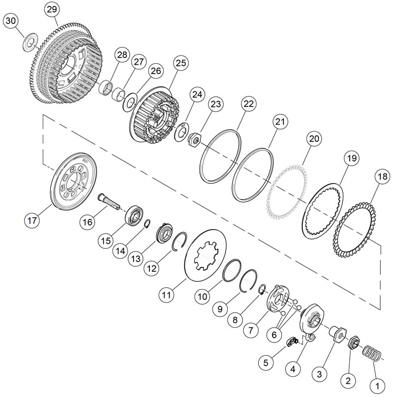
Figure 5-19. Clutch assembly: XR 1200X: 1. Spring; 2. Lockplate; 3. Nut; 4. Outer ramp; 5. Coupling; 6. Ball (3); 7. Inner ramp; 8. Retaining ring; 9. Retaining ring; 10. Spring seat; 11. Diaphragm spring; 12. Retaining ring; 13. Release plate; 14. Retaining ring; 15. Bearing; 16. Adjusting screw; 17. Pressure plate; 18. Friction plate, fiber (7); 19. Steel plate (7); 20. Friction plate, narrow, fiber; 21. Damper spring; 22. Damper spring seat; 23. Mainshaft nut; 24. Washer; 25. Clutch hub; 26. Inner thrust washer; 27. Needle bearing inner race; 28. Needle bearing; 29. Clutch shell and sprocket; 30. Outer thrust washer
Note. Transmission mainshaft nut (23) has left-hand threads. Turn nut clockwise to loosen and remove from mainshaft.
7. Remove nut (23) and spring washer (24). Remove the clutch assembly, primary chain and engine sprocket from the vehicle as an assembly.
8. Inspect primary chain. Replace as necessary.
9. Inspect stator and rotor. See 6.24 ALTERNATOR. Replace damaged parts as necessary.
Note. If replacement of primary chain is the only service work required, proceed directly to 5.5 PRIMARY DRIVE AND CLUTCH: XR 1200X, Installation. Skip Step 1 of that procedure and begin with the NOTE preceding Step 2.
Disassembly
| PART NUMBER | TOOL NAME |
| HD-38515-91 | CLUTCH SPRING FORCING SCREW |
| HD-38515-A | SPRING COMPRESSING TOOL |
1. See Figure 5-19. With clutch assembly removed from primary chaincase, install adjusting screw assembly (13, 14, 15 and 16) into pressure plate (17):
- a. Match the two tabs on perimeter of release plate (13) to the notches in pressure plate.
- b. Install the retaining ring (12).
Warning! Disassemble clutch using a spring compressing tool. The diaphragm spring is compressed and, if removed without proper tools can fly out, which could result in death or serious injury.
2. Assemble the compressing tool:
- a. Thread the CLUTCH SPRING FORCING SCREW (Part No. HD-38515-91) onto the clutch adjusting screw.
- b. Place the bridge of SPRING COMPRESSING TOOL (Part No. HD-38515-A) against diaphragm spring.
- c. Thread the tool handle onto end of forcing screw.
Note. Excessive compression of diaphragm spring could damage clutch pressure plate.
3. With a wrench on the clutch spring forcing screw flats to prevent the forcing screw from turning, turn handle clockwise until tool relieves pressure on retaining ring (9) and spring seat (10).
4. Remove and discard retaining ring. Remove spring seat from the groove in clutch hub prongs. Remove the diaphragm spring (11), pressure plate (17), adjusting screw components (13, 14, 15 and 16) and compressing tool as an assembly.
5. Turn the compressing tool handle counterclockwise until the clutch spring forcing screw disconnects from the clutch adjusting screw. Remove spring seat and diaphragm spring from pressure plate assembly.
6. Remove retaining ring (12) and adjusting screw assembly from pressure plate. If necessary, disassemble adjusting screw assembly. See 5.5 PRIMARY DRIVE AND CLUTCH: XR 1200X, Adjusting Screw.
7. Remove the clutch pack from the clutch hub. The clutch pack consists of seven friction (fiber) plates (18), seven steel plates (19), one narrow friction plate (20), one damper spring (21) and one seat (22).
Adjusting screw
1. See Figure 5-20. Remove adjusting screw assembly.
- a. Remove large retaining ring (1).
- b. Remove adjusting screw assembly from pressure plate (9).
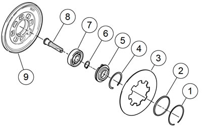
Figure 5-20. Adjusting screw assembly: 1. Retaining ring; 2. Spring seat; 3. Diaphragm spring; 4. Retaining ring; 5. Release plate; 6. Retaining ring; 7. Bearing; 8. Adjusting screw; 9. Pressure plate
2. If necessary, disassemble adjusting screw assembly.
- a. Remove and discard small retaining ring (6).
- b. Separate the adjusting screw (8) from the bearing (7) and release plate (5).
- c. Remove bearing (7) from release plate (5).
3. Replace components as required and reassemble adjusting screw assembly in reverse order.
4. Install adjusting screw assembly into pressure plate.
- a. See Figure 5-35. Align two tabs on perimeter of release plate with corresponding recesses (3) in pressure plate.
- b. Secure the adjusting screw assembly with new retaining ring.
Clutch pack cleaning and inspection
Steel plates
1. Wash the steel plates, and the damper spring and seat in solvent.
2. See Figure 5-21. Inspect each steel plate.
- a. Check for wear, grooves, or discoloration.
- b. Gauge warpage around the plate. If warpage exceeds specifications, replace the entire clutch pack. Refer to Table 5-5.
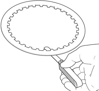
Figure 5-21. Gauging a steel plate
3. Inspect the damper spring and the spring seat. Replace as required.
Friction plates
Note. Do not wash the friction plates in solvent.
1. Wipe the friction plates clean of lubricant.
2. See Figure 5-22. Inspect each friction plate.
- a. Check for wear or discoloration.
- b. Measure the seven friction plates. If one thickness is less than specified, replace the entire clutch pack. Refer to Table 5-5.

Figure 5-22. Friction plate thickness
Table 5-5. Clutch pack plate specifications
| ITEM | SERVICE WEAR LIMIT | |
| in | mm | |
| CLUTCH PLATE THICKNESS | ||
| Friction plate (fiber) | 0.0795 | 2.0200 |
| Steel plate | N/A | N/A |
| MAXIMUM ALLOWABLE WARPAGE | ||
| Friction plate (fiber) | 0.0059 | 0.1500 |
| Steel plate | 0.0059 | 0.1500 |
Clutch shell/hub inspection
1. Inspect engine sprocket for damage or excessive wear. Replace as required.
2. Disassemble adjusting screw assembly and inspect bearing, release plate, and adjusting screw. See 5.5 PRIMARY DRIVE AND CLUTCH: XR 1200X, Adjusting Screw.
3. Remove clutch hub from clutch shell. Inspect primary chain sprocket and the starter ring gear on the clutch shell.
4. Inspect slots that mate with the clutch plates on both clutch shell and hub.
5. See Figure 5-23. Inspect the clutch shell compensating spring set.
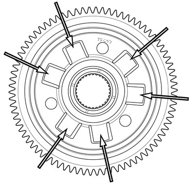
Figure 5-23. Compensating spring set
Note. It is possible for the compensating springs to float and move during inspection. This condition is normal.
6. See Figure 5-24. Inspect clutch shell needle bearing for smoothness. Rotate the clutch shell while holding the clutch hub. If bearing is rough or binds, it must be replaced. See 5.5 PRIMARY DRIVE AND CLUTCH: XR 1200X, Clutch Shell Bearing Replacement.

Figure 5-24. New needle bearing in clutch shell
7. See Figure 5-25. Inspect clutch shell bearing inner race on the back side of the clutch hub for pitting and wear. If the inner race shows any signs of damage, the complete hub assembly must be replaced.
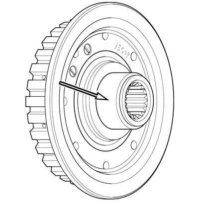
Figure 5-25. Clutch hub bearing race
8. Replace damaged parts as necessary.
Clutch shell bearing replacement
| PART NUMBER | TOOL NAME |
| B-45926 | CLUTCH SHELL BEARING REMOVER/INSTALLER |
Note. The clutch shell uses a caged needle bearing that corresponds to an inner race installed on the clutch hub.
1. See Figure 5-27. Place clutch shell on support blocks with sprocket side facing up.
Note. The CLUTCH SHELL BEARING REMOVER/INSTALLER (Part No. B-45926) is clearly marked for removal and installation purposes.
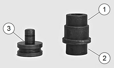
Figure 5-26. Clutch shell bearing remover/installer: 1. Removal end of bearing tool; 2. Installation end of bearing tool; 3. Bearing guide, installer
2. See Figure 5-27. Insert removal end of tool into bearing assembly and remove bearing from clutch shell.
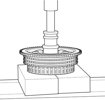
Figure 5-27. Removing clutch shell needle bearing
3. See Figure 5-28. Remove bearing guide from end of CLUTCH SHELL BEARING REMOVER/INSTALLER (Part No. B-45926).
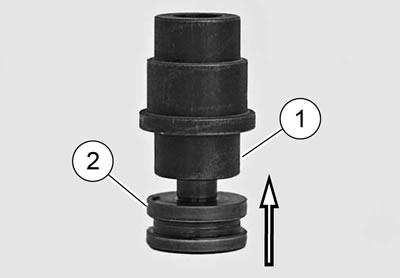
Figure 5-28. Bearing installer: 1. Place needle bearing on tool in this location; 2. Bearing guide
4. Place new needle bearing onto installer end of tool and insert the bearing guide.
5. See Figure 5-29. Place clutch shell on support blocks with sprocket side facing up.

Figure 5-29. Installing clutch shell needle bearing: 1. Needle bearing; 2. Clutch shell
6. Press bearing into clutch shell until tool bottoms on the shell. This will be the correct installed height.
Assembly
| PART NUMBER | TOOL NAME |
| HD-38515-A | SPRING COMPRESSING TOOL |
1. Submerge and soak all friction and steel plates in GENUINE HARLEY-DAVIDSON FORMULA+ TRANSMISSION AND PRIMARY CHAINCASE LUBRICANT for at least five minutes.
2. See Figure 5-30. Install narrow friction plate on the clutch hub, engaging tabs on plate with slots in clutch shell.
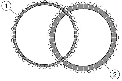
Figure 5-30. Friction plates: 1. Narrow plate; 2. Regular plate
3. See Figure 5-31. Install damper spring seat (1) on clutch hub so that it seats inboard of narrow friction plate (3).
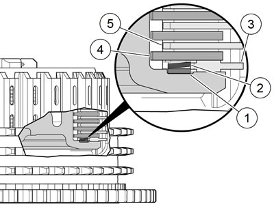
Figure 5-31. Clutch pack stack-up: 1. Damper spring seat; 2. Damper spring; 3. Narrow friction plate; 4. Steel plate; 5. Friction plate
4. Install damper spring (2) on clutch hub with the concave side up (facing opposite damper spring seat).
5. Install a steel plate (4) and then a friction plate (5) on the clutch hub. Install six remaining sets in the same manner, alternating between steel plates and friction plates.
6. Place pressure plate, diaphragm spring, adjusting screw assembly with new retaining ring and spring seat onto clutch pack.
7. Install the retaining ring:
- a. See Figure 5-32. Align square openings of pressure plate and diaphragm spring so that the assembly can be installed over prongs on clutch hub.
- b. Position spring seat with its larger outer diameter side toward diaphragm spring.
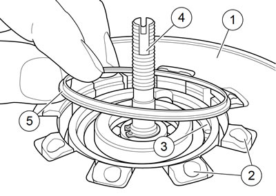
Figure 5-32. Spring seat installation: 1. Diaphragm spring (pressure plate below); 2. Prongs on clutch hub; 3. Retaining ring; 4. Adjusting screw assembly; 5. Spring seat
Note. Turn compressing tool handle only the amount required to install spring seat and retaining ring. Excessive compression of diaphragm spring could damage clutch pressure plate.
- c. Install SPRING COMPRESSING TOOL (Part No. HD-38515-A) onto clutch hub against diaphragm spring.
- d. Place a wrench on the clutch spring forcing screw flats to prevent the forcing screw from turning.
- e. Turn compressing tool handle clockwise until diaphragm spring compresses just enough to install new retaining ring into the groove in clutch hub prongs.
- f. With retaining ring fully seated in groove of clutch hub, remove the compression tool.
Note. Remove the tool to allow the diaphragm spring to move outward forcing the spring seat up into the inside of the retaining ring. The spring seat is an operating surface for the diaphragm spring and prevents the retaining ring from coming out.
Installation
| PART NUMBER | TOOL NAME |
| HD-38362 | SPORTSTER 5-SPEED SPROCKET LOCKING LINK |
| HD-46283 | PRIMARY DRIVE LOCKING TOOL |
| FASTENER | TORQUE VALUE | |
| Engine sprocket bolt: XR 1200X | 155-165 ft·lbs | 210.0-224.0 Nm |
| Transmission mainshaft nut: XR 1200X | 50-60 ft·lbs | 67.8-81.3 Nm |
1. See Figure 5-19. Remove retaining ring (12). Remove adjusting screw assembly (13, 14, 15, 16) from pressure plate (17) to allow installation of the transmission mainshaft nut and washer.
Note. Prior to installing engine sprocket bolt and transmission main-shaft nut, thoroughly clean threads of engine sprocket shaft, transmission mainshaft and mainshaft nut to remove any oil that might contaminate and interfere with locking agent.
2. Thoroughly clean threads of engine sprocket shaft, transmission mainshaft and mainshaft nut to remove any oil.
Notes:
- See Figure 5-33. Do not position the sprocket locking link (1)too close to the shifter shaft (2). The sprocket locking can damage the shifter shaft and/or engine crankcase.
- Japan models use PRIMARY DRIVE LOCKING TOOL (Part No. HD-46283).
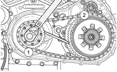
Figure 5-33. Tighten engine sprocket bolt: 1. Sprocket locking link; 2. Shifter shaft
3. See Figure 5-33. Install SPORTSTER 5-SPEED SPROCKET LOCKING LINK (Part No. HD-38362) (1).
4. Install new engine sprocket bolt. Tighten to 155-165 ft·lbs (210.0-224.0 Nm).
Note. See Figure 5-34. Washer (2) must be installed with the word "out" facing the transmission mainshaft nut (1). Incorrect assembly can result in clutch and/or transmission failure.
5. Install mainshaft nut.
- a. See Figure 5-34. Apply two or three drops of LOCTITE 262 HIGH STRENGTH THREADLOCKER AND SEALANT (red) onto threads of transmission main-shaft.
- b. Install spring washer (2) and mainshaft nut (1) (lefthand threads) on transmission mainshaft.
- c. Tighten to 50-60 ft·lbs (67.8-81.3 Nm).
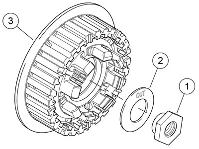
Figure 5-34. Mainshaft nut and washer: 1. Mainshaft nut; 2. Washer; 3. Clutch hub
6. Remove the sprocket locking link.
7. See Figure 5-35. Install adjusting screw assembly in pressure plate with two tabs on perimeter of release plate matched to recesses in pressure plate. Secure with a new retaining ring.
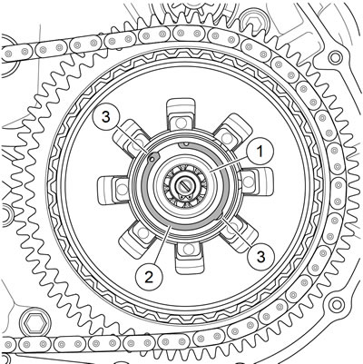
Figure 5-35. Clutch adjusting screw assembly and retaining ring: 1. Adjusting screw assembly; 2. Retaining ring; 3. Tab recesses
8. Install primary cover using new gasket. See 5.3 PRIMARY COVER.
9. Adjust primary chain and clutch. See 1.9 PRIMARY CHAIN and 1.11 CLUTCH.
10. Fill transmission. See 1.10 TRANSMISSION LUBRICANT.
11. Connect battery and close left side cover. See 1.22 BATTERY MAINTENANCE.