Removal
Note. If bearing races are removed, the bearings cannot be reused-they must be replaced. See Cleaning and inspection in 2.29 Steeping head.
1. Support motorcycle so front end is off floor and forks are fully extended.
2. Remove right side cover and maxi-fuse. See 8.5 Maxi-fuse.
3. Remove headlamp and headlamp bracket. See 2.21 Handlebars.
4. Remove both front brake calipers. See 2.18 Front brake calipers.
5. Remove front wheel. See 2.22 Front wheel.
6. Remove front fender bracket with front fender. See 2.27 Front fender.
7. Loosen but do not remove fork tube caps.
8. See Figure 2-94. Loosen pinch bolts (5) on top and bottom tripe clamps and pull fork tubes from triple clamps. See 2.28 Front fork.

Figure 2-94. Steering head: 1. Cap; 2. Nut; 3. Lockwasher; 4. Upper triple clamp; 5. Pinch bolt; 6. Fall-away adjusting nut; 7. Seal; 8. Upper bearing; 9. Bearing cup; 10. Fork stem; 11. Bearing cup; 12. Lower bearing; 13. Seal; 14. Lower triple clamp; 15. Retaining ring
9. Remove brake hose bracket from the bottom of fork stem (10) and bracket.
10. Remove fork stem cap (1). Bend lockwasher (3) tab away from fork stem nut (2). Remove fork stem nut.
11. Lift handlebars from steering head with upper triple clamp (4) attached. Be careful not to pinch or kink control cables.
12. Remove adjusting nut (6), seal (7), and upper bearing (8) out of bearing race.
13. Pull fork stem (10) and lower triple clamp (14) from bottom of steering head.
Cleaning and inspection
1. Check upper and lower bearing races in steering head. If they are pitted or grooved, replace bearings and races in sets.
2. Check roughness of bearings by turning them in race. Replace bearings if they do not turn freely and smoothly.
Caution! Always replace both races and bearings even if one race and bearing appear to be good. Mismatched bearing components may lead to excessive wear and the need for premature bearing replacement.
Lower fork stem bearing
| PART NO. | SPECIALTY TOOL |
| HD-95637-46A | Universal wedge attachment |
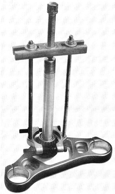
1. See Figure 2-95. Assemble a bearing puller using a using a UNIVERSAL WEDGE ATTACHMENT (HD-95637-46A), two lengths of threaded rod, washers, nuts, a cross clamp or bridge, and a forcing screw and a washer or protective cap.

Figure 2-95. Bearing puller based on universal wedge attachment
2. Turn forcing screw to remove bearings and seal from lower triple clamp.
Steering head bearing race
| PART NO. | SPECIALTY TOOL |
| HD-33416 | Universal driver handle |
| HD-39301-A | Steering head bearing race remover |
1. See Figure 2-96. With the tapered side down, seat STEERING HEAD BEARING RACE REMOVER (HD-393201-A) on upper bearing race leaving a gap in middle and with lower lip of removers capturing bottom edge of bearing race.

Figure 2-96. Race remover tools (HD-33416 and HD-39301-A): 1. Remover (2 halves); 2. Collet; 3. Driver
2. Install collet on driver.
3. Insert UNIVERSAL DRIVER HANDLE (HD-33416) at bottom of steering head tube, and while holding remover tool on race, center collet in gap between remover halves. Tap driver to remove upper race.
4. Reverse tool and repeat procedure to remove lower bearing race.
Assembly
| PART NO. | SPECIALTY TOOL |
| HD-39302 | Steering head bearing race installer |
1. Lubricate outside of new steering head bearing races with lubricant provided or engine oil.
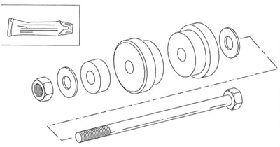
2. See Figure 2-97. Assemble STEERING HEAD BEARING RACE INSTALLER (HD-39302) and bearing races on tool’s draw down bolt through steering head. Orient races so lettered edges are at bottom of steering head bore in steering head.

Figure 2-97. Steering head bearing race installer (HD-39302)
3. Continue to thread nut on draw down bolt until races fit, and are parallel to steering head bore.
4. Slowly tighten nut while stopping periodically to check for bearing race to steering head parallelism.
Warning! Use care not to damage the new races’ tapered surface. The race should be firmly seated against the shoulder in the bore. If it is loose, the steering head adjustment will become loose, adversely affecting the motorcycle’s handling, which may lead to an accident which could result in death or serious injury.
5. When bearing races are fully seated in bore of steering head, pack new bearings with HARLEY-DAVIDSON SPECIAL PURPOSE GREASE (HD-99857-97).
Caution! Do not use a sleeve that is larger than the inner race of the bearing or bearing cage may be damaged. A damaged bearing cage will require replacement of both the cage and the bearing.
6. Install a new lower seal on fork stem.
7. Use sleeve or drift that will contact only inner race of bearing and press lower bearing into place on fork stem.
Note. A sleeve (drift) to press on the lower fork stem bearing can be constructed out of thick walled pipe, 22.86 cm (9.0 in.) long with an inside diameter of 25.65 mm (1.010 in.) and an outside diameter of 31.75 mm (1.250 in.).
Installation
1. See Figure 2-94. Insert fork stem (10) and lower triple clamp (14) assembly into frame steering head and install a new upper bearing (8) and new seal (7). Secure with adjusting nut (6). Tighten adjusting nut until bearings have no noticeable shake. Fork stem must turn freely from side to side.
Caution! Overtightening adjusting nut will cause the bearings to wear excessively leading to the need for premature bearing replacement.
2. Install upper triple clamp (4), a new lockwasher (3). Be sure pin on lockwasher registers in upper bracket hole.
Warning! An improperly adjusted fork stem nut may adversely affect handling, which could lead to an accident which could result in death or serious injury.
3. Thread on and finger tighten fork stem nut (2).
4. Fasten brake hose bracket to lower triple clamp (14). Tighten bolt to 6-10 Nm (53-89 in-lbs).
5. Install fork tube assemblies into bottom and top triple clamps (4, 14).
6. See Figure 2-93. The fork tube should project above upper triple clamp 0.64-0.97 mm (0.25-0.038 in.). Tighten pinch bolts to 41-47 Nm (31-34 ft-lbs).
7. Install handlebar brackets, handlebars, clutch and brake lever assemblies.
8. Install headlamp assembly. See 2.21 Handlebars.
9. Install front fender and bracket. See 2.27 Front fender.
10. Install front wheel assembly. See 2.22 Front wheel.
11. Install right and left front brake calipers. See 2.18 Front brake calipers.
12. Adjust steering head bearing fall away. Tighten or loosen adjuster nut until the fall away measurement is within 127-178 mm (5.0-7.0 in.). See 2.29 Steering head.
13. See Figure 2-94. Tighten fork stem nut (2) to 61-75 Nm (45-55 ft-lbs). Bend the lockwasher (3) tab against nut flat.
14. Replace fork stem cap (1).
