Removal
Note. Mark all hardware as it is removed so that it may be returned to its original location.
1. Remove right side cover and maxi-fuse.
2. Remove belt guard and debris deflector. See 2.31 Belt guard/debris deflector.
3. Remove rear wheel. See 2.23 Rear wheel.
4. Remove rear brake caliper brake fluid line from clips on rear fork. See 2.20 Rear brake caliper.
5. Remove left lower rear shock absorber bolt. Remove right rear shock absorber bolt and thin height nut. See 2.32 Rear shock absorbers.
Note. Block or support engine before removing pivot shaft.
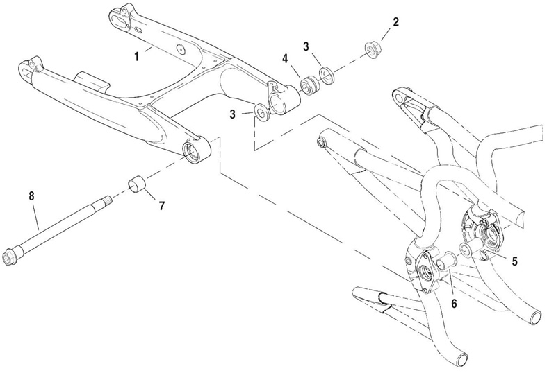
6. See Figure 2-101. Remove pivot shaft nut (2).

Figure 2-101. Rear fork: 1. Rear fork; 2. Pivot shaft nut; 3. Dust seal; 4. Left pivot bearing assembly; 5. Left spacer; 6. Right spacer; 7. Right pivot bearing; 8. Pivot shaft
7. Support rear fork and slide pivot shaft (8) out of rear fork. Rear fork (1) can now be removed from frame. Discard dust seals (3).
Note. The left and right pivot spacers (5, 6) will remain inside the motor mounts.
Disassembly
Note. Remove left pivot bearing assembly from fork only if replacement is required. The complete bearing assembly must be replaced as a unit when replacement is necessary. Do not intermix bearing components.
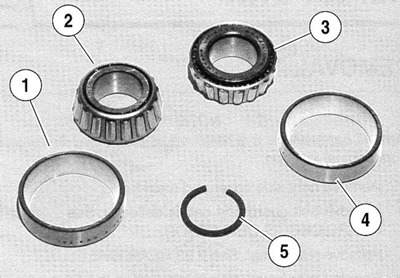
1. See Figure 2-102. Remove left pivot tapered bearings and bearing spacer.

Figure 2-102. Left pivot bearing components: 1. Inboard bearing race; 2. Inboard tapered bearing; 3. Outboard tapered bearing; 4. Outboard bearing race; 5. Bearing spacer
2. Use a brass drift to drive out inboard and outboard bearing races.
3. See Figure 2-103. Using a die grinder, grind a spot to weaken c-clip bearing race separator at a point 180° opposite the open end. Pry out and break at grind point.

Figure 2-103. C-clip bearing race separator in left pivot bore
4. Remove remaining c-clip half.
5. See Figure 2-101. Carefully press right side bearing (7) from fork.
6. Clean all components in solvent and blow dry. Carefully inspect all bearing components for wear and/or corrosion.
7. Check that rear fork is not bent or twisted. Replace it if it is damaged.
Assembly
1. See Figure 2-101. Carefully press new right side bearing (7) into fork.
2. See Figure 2-103. Snap new c-clip into groove in center of left side pivot bore.
3. See Figure 2-102. Press new inboard (1) and outboard (4) bearing races into pivot bore.
4. Pack the new tapered bearings (2, 3) with HARLEY DAVIDSON WHEEL BEARING GREASE (HD-99855-89)
5. Install inboard bearing, bearing spacer, and outboard bearing into bearing races.
6. See Figure 2-101. Fit new dust seals (3) over left and right sides of bearings.
7. With soft hammer, tap dust seals into place.
Installation
1. Slide rear fork assembly into position.
2. See Figure 2-101. From right side, slide pivot shaft (8) through dust seals (3), rear fork pivot bearings (4, 7) and engine mounts, spacers (5, 6).
3. Apply two or three drops of LOCTITE® 243 (blue) to threads of pivot shaft nut (2). Install and tighten pivot shaft nut (2) to 61-75 Nm (45-55 ft-lbs).
Note. Proper pivot shaft tightening is important to maintain rear fork alignment.
4. Check for freedom of rotation of rear fork around bearings and that fork and frame side rails have not been distorted when pivot shaft nut was tightened.
5. Install both rear shock absorbers. See 2.32 Rear shock absorbers.
6. Install rear brake caliper and clip brake line to rear fork. See 2.20 Rear brake caliper.
7. Install rear wheel. See 2.23 Rear wheel.
8. Install belt guard and debris deflector. See 2.31 Belt guard/debris deflector.
9. Install maxi-fuse and right side cover.
