Removal
1. Support motorcycle so front end is off floor and forks are fully extended.
2. Remove right side cover and maxi-fuse. See 8.5 Maxi-fuse.
3. Remove airbox cover. See 1.4 Airbox and air filter.
4. Remove negative battery cable.
5. Remove both front brake calipers. See 2.18 Front brake calipers.
6. Remove front wheel. See 2.22 Front wheel.
7. Remove front fender bracket with the front fender. See 2.27 Front fender.
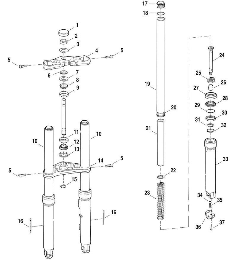
8. See Figure 2-90. On one side, first loosen pinch bolt (5) on top triple clamp (4).

Figure 2-90. Front fork/steering head components: 1. Cap - fork stem; 2. Nut - fork stem; 3. Lockwasher - fork stem nut; 4. Top triple clamp; 5. Pinch bolts; 6. Adjusting nut - upper; 7. Seal; 8. Roller bearing; 9. Bearing cup; 10. Fork tube and slider assembly (right & left); 11. Bearing cup; 12. Tapered roller bearing; 13. Seal; 14. Bottom triple clamp; 15. Retaining ring; 16. Reflector; 17. Fork tube cap; 18. O-ring; 19. Fork tube (right & left); 20. Bushing; 21. Spring collar; 22. Washer; 23. Rebound spring; 24. Seat pipe; 25. Spring; 26. Stop oil lock piece; 27. Slider cover; 28. Dust shield; 29. Stopper ring; 30. Oil seal; 31. Seal spacer; 32. Bushing guide; 33. Slider; 34. Washer; 35. Seat pipe screw; 36. Axle holder; 37. Axle holder screw
9. Break loose but do not remove fork tube cap (17).
10. Loosen pinch bolts (5) on bottom triple clamp (14) and pull fork tube and slider assembly (10) from triple clamp.
11. Repeat procedure for opposite fork tube and slider assembly (10).
Disassembly
| PART NO. | SPECIALTY TOOL |
| HD-41177 | Fork tube holder |
1. See Figure 2-87. Clamp fork tube and slider assembly in FORK TUBE HOLDER (HD-41177) and mount in vise.

Figure 2-87. Fork tube holder (hd-41177) (mounted vertically to slider)
2. See Figure 2-90. While internal components are still under tension and less prone to rotate, break loose but do not completely unthread seat pipe screw (35). On right fork tube and slider assembly, remove axle holder (36) to access seat pipe screw.
Warning! The fork tube caps are under spring pressure. Always wear proper eye protection when removing fork tube caps. The spring can force parts from the tube unexpectedly, which could result in death or serious injury.
3. Remove fork tube cap (17) and o-ring (18).
4. Remove the long spring collar (21).
5. Remove from FORK TUBE HOLDER and invert fork over a suitable container. Allow fork to drain. Extend and retract slider several times to push oil out of internal components. The washer (22), and spring (23) will fall out of fork tube.
6. Clamp fork tube in holder. Mount FORK TUBE HOLDER (HD-41177) horizontally in vise.
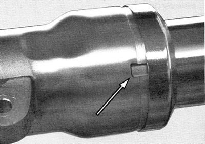
7. Remove slider cover (27) from slider by inserting brass drift into notch in slider and lightly tapping cover.

Figure 2-88. Notch in slider
8. Compress stopper ring (29) and remove stopper ring from groove in top of slider bore.
Warning! The VRSCA models have a preloaded fork spring. The seat pipe is under spring pressure. Always wear proper eye protection when disassembling the fork tube and slider assembly. Disassemble the fork tube and slider assemblies carefully. The springs can force parts from the fork tube or slider unexpectedly, which could result in death or serious injury.
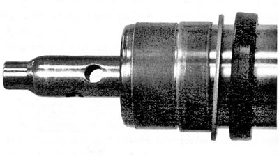
9. Remove seat pipe screw (35) and washer (34) from bottom of slider (33). Retain the seat pipe screw and washer.

Figure 2-89. Seat pipe screw (right fork assembly)
10. Withdraw slider (33) from fork tube (19) until bushing guide (32) contacts bushing (20) on fork tube. Busing guide (32) is a slight interference fit in slider.
11. Using the slider as a slide hammer, hit the bushing with the bushing guide with a quick continuous stroke until slider is pulled free of the fork tube.
12. Drain the slider and allow the stop oil lock piece (26) to fall free.
Note. If replacing the slider only, the components remaining in the fork tube can be left assembled and the fork re-assembled from ASSEMBLY procedures step 5.
13. If still attached to seat pipe, remove stop oil lock piece (26) from the lower end of seat pipe.
14. Remove seat pipe (24) piston and ring assembly.
15. Remove rebound spring (23).
16. Remove oil seal (30), seal spacer (31), and bushing guide (32).
17. Repeat procedure for opposite fork tube and slider assembly (10).
Cleaning and inspection
1. Thoroughly clean and inspect each part. If inspection shows that any parts are bent, broken or damaged, those parts should be repaired or replaced.
2. Inspect fork tube bushing and slider guide bushing and replace as required.
3. Always replace oil seals and o-rings.
4. Check dust cover where it rubs on fork tube. The dust cover should present a good continuous seal and not show excessive wear.
5. Check the fork tube where it rubs on dust cover. The tube should show a bright, shining surface, free of scoring or abrasions.
6. If springs are broken, replace springs.
7. If a fork tube or slider is bent or damaged, replace it.
8. Replace all other worn or damaged components as necessary.
Assembly
| PART NO. | SPECIALTY TOOL |
| HD-41177 | Fork tube holder |
| HD-45305 | Fork seal driver |
| HD-59000A | Pro-level oil gauge |
1. See Figure 2-90. Insert seat pipe and piston assembly (24) with the rebound spring (23) into fork tube (19).
2. Slide bushing guide (32) down to bushing (20) on fork tube (19). Follow with spacer (31), oil seal (30), stopper ring (29), dust shield (28) and slider cover (27).
3. Install fork tube into FORK TUBE HOLDER (HD-41177) mounted horizontally in a vise.
4. Fit stop oil lock piece (26) onto seat pipe (24).
5. See Figure 2-91. Side seat pipe back into fork tube until seat pipe is centered in tube.

Figure 2-91. Seat pipe centered in fork tube
6. See Figure 2-90. Gently install slider (33) onto fork tube (19) and bushing (20).
7. Thread seat pipe screw (35) and washer (34) into seat pipe (24) through bottom of slider (33). Draw fastener into seat pipe but do not torque.
8. Verify action of fork by sliding slider up and down fork tube.
9. Assemble the FORK SEAL DRIVER (Part No. HD-45305) over fork tube in front of oil seal.
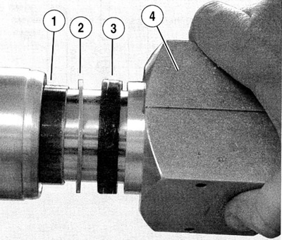
10. See Figure 2-92. Holding FORK SEAL DRIVER (4) together, tap oil seal (3), spacer (2) and bushing guide (1) into slider bore.

Figure 2-92. Assembled fork seal driver: 1. Bushing guide; 2. Spacer; 3. Oil seal; 4. Fork seal driver
11. See Figure 2-90. Install stopper ring (29) into groove in top of oil seal.
12. Push dust shield (28) against oil seal and stopper ring
13. Rotate slider cover to match any removal burrs to notch in slider and snap slider cover (27) into place.
14. Move slider through its full range of travel several times to verify alignment. Then, pulling down on slide to apply downward force on rebound spring (23), tighten seat pipe screw to 12-18 Nm (106-159 in-lbs).
15. Re-position fork tube in FORK TUBE HOLDER (HD-41177) vertically. With slider tube compressed, fill the fork with Harley-Davidson TYPE E FORK OIL (Part No. HD-99884-80) until it is approximately 85 mm (3.3 in.) from top of fork tube. See 1.18 Front fork oil.
16. Slowly pump slider 8 to 10 times to exhaust air from assembly. Fully compress slider to determine oil level.
Note. Fork oil level is measured from top of fork tube, with spacer and spring removed and fork fully compressed.
17. Using the PRO-LEVEL OIL GAUGE (HD-59000A), adjust the oil level to 85 mm (3.3 in.) from top of fork tube.
18. Pull out the slider (33) and install the rebound spring (23) in the fork tube with the tightly wound end at the bottom.
19. Install the washer (22) and spring collar (21).
Warning! The fork tube caps are under spring pressure. Always wear proper eye protection when removing/installing fork tube caps.The spring can force parts from the tube unexpectedly, which could result in death or serious injury.
20. With a new о-ring, install and tighten fork tube caps to 22-58 Nm (16-43 ft-lbs).
Note. To prevent cross threading fork tube caps, use caution when threading in the caps with the spring compressed.
21. Repeat for opposite fork tube and slider assembly.
Installation
1. See Figure 2-93. Insert fork tube and slider assemblies through lower triple clamp and upper triple clamp, fork tubes should project above upper triple clamp 6.4-9.7 mm (0.25-0.38 in.). Tighten pinch bolts to 41-47 Nm (31-34 ft-lbs).

Figure 2-93. Fork tube projection (6.4-0.7 mm)
2. Install front fender and bracket. See 2.27 Front fender.
3. Install front brake caliper hydraulic lines and install front brake calipers. See 2.18 Front brake calipers.
4. Install front wheel and align the wheel to the forks. See 2.22 Front wheel.
5. Adjust fall-away. See 1.17 Steering head bearings.
6. Replace negative battery cable. Tighten to 6.8-10.8 Nm (60-96 in-lbs).
7. Replace airbox cover
8. Replace maxi-fuse and right side cover.
