Removing socket/pin terminals
1. Remove connector from the retaining device, either attachment or rosebud clip.
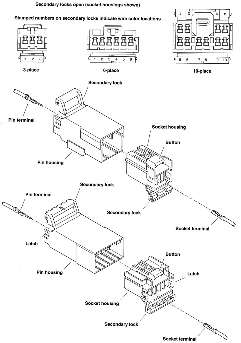
2. Depress the button on the socket terminal side of the connector (plug) and pull apart the pin and socket halves.
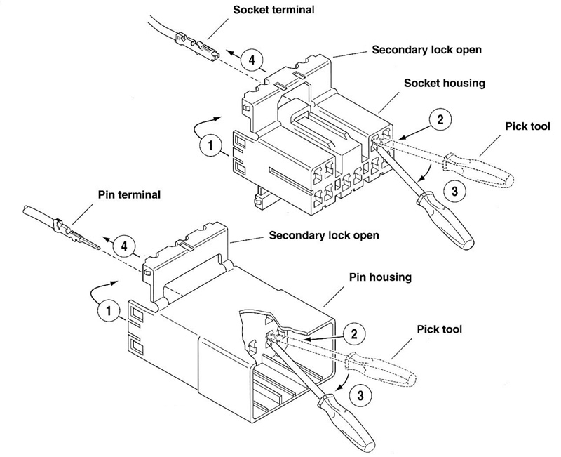
3. Bend back the latch slightly and free one side of secondary lock, then repeat the step to release the other side. Rotate the secondary lock outward on hinge to access terminals in chambers of connector housing.
4. Looking in the terminal side of the connector (opposite the secondary lock), take note of the cavity next to each terminal.
5. See Figure B-1. With the flat edge against the terminal, insert the pick tool (Snap-on TT600-3) into the cavity until it stops. Pivot the end of the pick away from the terminal (locktab is inside housing) and gently tug on wire to pull terminal from chamber. Do not tug on the wire until the tang is released or the terminal will be difficult to remove. A "click" is heard if the tang is engaged but then inadvertently released. Repeat the step without releasing the tang.

Figure B-1. 10-Place AMP multilock connector
Notes:
- If pick tool is not available, a push pin/safety pin may be used instead.
- An ELECTRICAL TERMINAL CRIMP TOOL (Part No. HD-41609) is used to install AMP Multilock pin and socket terminals on wires. If new terminals must be installed, see Crimping Instructions on the next page.
Installing socket/pin terminals
Note. For wire location purposes, numbers are stamped into the secondary locks of both the socket and pin housings. See Figure B-2.

Figure B-2. Release tang and back out terminals: 1. Open secondary lock; 2. Insert pick into cavity on inboard side of connector; 3. Pivot end of pick to release tang; 4. Gently tug on wire to remove terminal from housing.
1 . From the secondary lock side of the connector, insert the terminal into its respective numbered chamber until it snaps in place. For proper fit, the slot in the terminal must face the tang in the chamber.
Notes:
- See Figure B-3. The tang in the chamber engages the slot to lock the terminal in position.
- On the pin side of the connector, tangs are positioned at the bottom of each chamber, so the slot in the pin terminal (on the side opposite the crimp tails) must face downward.
- On the socket side, tangs are at the top of each chamber, so the socket terminal slot (on the same side as the crimp tails) must face upward.
- Up and down can be determined by the position of the release button (used to separate the pin and socket halves). Consider the button to always be on top of the connector.

Figure B-3. Multilock connector cutaway view
2. Gently tug on wire end to verify that the terminal is locked in place and will not back out of chamber.
3. Rotate the hinged secondary lock inward until tabs fully engage latches on both sides of connector.
4. Insert the socket housing (plug) into the pin housing (receptacle) until it snaps in place.
5. Install connector on retaining device, either attachment or rosebud clip.
Crimping instructions
1. Squeeze the handles to cycle the crimp tool (Part No. HD-41609) to the fully open position.
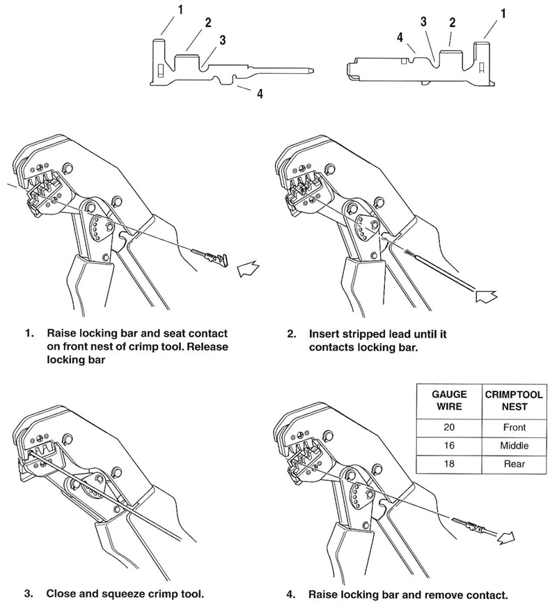
2. Raise locking bar by pushing up on bottom flange. With the crimp tails facing upward, insert contact (socket/pin) through locking bar, so that the closed side of the contact rests on the front nest (concave split level area of the crimp tool). See Figure B-3.
3. Release locking bar to lock position of contact. When correctly positioned, the locking bar fits snugly in the space at the front of the core crimp tails.
4. Strip lead removing 5/32 in. (4 mm) of insulation. Insert wires between crimp tails until ends make contact with locking bar. Verify that wire is positioned so that short pair of crimp tails squeeze bare wire strands, while long pair folds over insulation material.
5. Squeeze handle of crimp tool until tightly closed. Tool automatically opens when the crimping sequence is complete. Raise up locking bar and remove contact.
6. Inspect the quality of the core and insulation crimps. Distortion should be minimal.

Figure B-4. 3-Place and 6-Place AMP multilock connectors

Figure B-5. AMP multilock crimping procedure: 1. Insulating crimp tail; 2, Core crimp tail; 3. Locking bar groove; 4. Tang slot
