General
From a servicing standpoint, there are two basic types of Packard electrical connectors, those with pull-to-seat terminals and those with push-to-seat terminals.
Look into the mating end of the connector. If it appears that the terminal can be extracted from this side, then it is probably the pull-to-seat type.
At least one Packard pull-to-seat terminal can be easily recognized by the presence of a locking ear. The ear engages a slot in the connector housing and prevents the terminal from being removed from the wire end side of the connector. The ear also acts as a strain relief in the event that the wires are pulled and further inhibits movement of the terminal inside the chamber.
Unlike most connectors, where the terminals are pulled out the wire end of the connector, to remove the terminals from the pull-to-seat connectors, the terminal is pushed out the mating end of the connector. Once a new terminal is crimped onto the end of the wire, the wire is pulled to draw the terminal back inside the chamber of the connector housing.
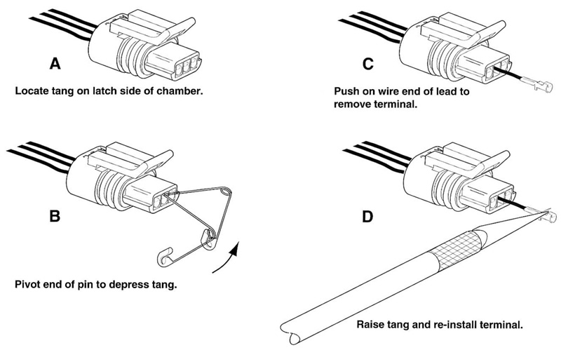
Two types of Packard pull-to-seat electrical connectors are used. One type has an external latch to lock the pin and socket halves together, while the other makes use of a wireform. See Figure B-20. The manner in which the terminals are picked differs between these two types of connectors, as further described below.

Figure B-20. Packard connectors
Pull-to-seat terminals
Removing external latch type
To remove a pull-to-seat terminal from connectors with external latches, proceed as follows:
1. Remove the connector from the retaining device, if present.
2. Bend back the external latch(es) slightly and separate the pin and socket halves of the connector.
3. To free a pull-to-seat terminal from the connector housing, first look into the mating end of the connector to find the locking tang. See A in Figure B-20. The tangs are always positioned in the middle of the chamber and are on the same side as the external latch. On those connectors with locking ears, the tang is on the side opposite the ear.
4. At a slight angle, gently insert the point of a one inch safety pin down the middle of the chamber (about 1/8 inch) and pivot the end of the pin toward the terminal body. When a click is heard, remove the pin and repeat the procedure. See В in Figure B-20. The click is the sound of the tang returning to the locked position as it slips from the point of the pin. Pick at the tang in this manner until the clicking stops and the pin seems to slide in at a slightly greater depth than it had previously. This is an indication that the tang has been depressed.
Notes:
- On those terminals that have been extracted on a previous occasion, no clicking sound may be heard when the pin is pivoted to depress the tang, but proceed as if the clicking is audible and then push on the wire end of the lead to check if the terminal is free.
- When picking multiple terminals, the end of the pin may become malleable. For best results, continue the procedure with a new safety pin.
5. Remove the pin and push on the wire end of the lead to extract the terminal from the mating end of the connector. See C in Figure B-20. If necessary, pull back the conduit and remove the wire seal at the back of the connector to introduce some slack in the wires.
Note. A series of Packard Electrical Terminal Crimp Tools are available to install Packard pin and socket terminals on wires. If new terminals must be installed, see Crimping Instructions.
Installing external latch type
Note. For wire location purposes, alpha characters are stamped into the socket housings.
1. To install a terminal back into the chamber of the connector housing, use a thin flat blade, like that on an X-Acto knife, and carefully bend the tang outward away from the terminal body. See D in Figure B-20.
2. Gently pull on the lead at the wire end of the connector to draw the terminal back into the chamber. A click is heard when the terminal is properly seated.
3. Push on the lead to verify that the terminal is locked in place.
4. Push the pin and socket halves of the connector together until the latches "click."
Push-to-seat terminals
Removing push-to-seat terminals
Like most connectors, Packard push-to-seat terminals are pulled out the wire end of the connector. To remove a push-to-seat terminal, proceed as follows:
1. Remove the connector from the retaining device, if present.
2. Bend back the external latch(es) slightly and separate the pin and socket halves of the connector.
Note. Both the Ignition Light/Key Switch and the Main Power connectors are provided with secondary locks. The secondary lock, which may be molded onto the connector or exist as a separate piece, aids in terminal retention. Secondary locks must be opened (or removed) before the terminals can be extracted from the connector housing.
3. Open or remove the secondary lock. Ignition Switch: Bend back the latch slightly and free one side of the secondary lock, then repeat the step to release the other side. Rotate the secondary lock outward on hinge to access the terminals in the chambers of the connector housing.
4. Looking in the mating end or terminal side of the connector (opposite the secondary lock), take note of the larger cavity next to each terminal.
5. Insert the pick (Snap-On TT600-3) into the cavity until it stops. Pivot the end of the pick toward the terminal to depress the locking tang. Remove the pick and gently tug on the wire to pull the terminal from the wire end of the connector. Repeat the step if the terminal is still locked in place.
Note. A series of Packard Electrical Terminal Crimp Tools are available to install Packard pin and socket terminals on wires. If new terminals must be installed, see Crimping Instructions.
Installing push-to-seat terminals
Note. For wire location purposes, alpha characters are stamped onto the secondary locks or onto the wire end of the connector housing.
1. To install a terminal back into the chamber of the connector housing, use a thin flat blade, like that on an X-Acto knife, and carefully bend the tang outward away from the terminal body.
2. Push the lead into the chamber at the wire end of the connector. A click is heard when the terminal is properly seated.
3. Gently tug on the wire end to verify that the terminal is locked in place and will not back out of the chamber.
4. Close or install the secondary lock. Ignition Switch: Rotate the hinged secondary lock inward until tabs fully engage latches on both sides of connector.
5. Push the pin and socket halves of the connector together until the latches "click."
6. Install connector on retaining device, if present.
Crimping instructions
1. Strip wire lead removing 5/32 in. (4 mm) of insulation.
2. Compress handles until ratchet automatically opens.
Note. Always perform core crimp before insulation/seal crimp.
3. Determine the correct dye or nest for the core crimp by checking with the appropriate crimp table.
Note. When the word "TIP" appears in the Crimp Table, use the tip of the tool specified to perform the core crimp procedure. See Figure B-21.

Figure B-21. Packard terminal crimp tools
4. Lay the back of the core crimp tails on the appropriate nest. Be sure the core crimp tails are pointing towards the forming jaws.
5. Gently apply pressure to handles of tool until crimpers slightly secure the core crimp tails.
6. Insert stripped wire between crimp tails. Verify that wire is positioned so that short pair of crimp tails squeeze bare wire strands, while long pair folds over insulation or seal material.
7. Squeeze handle of crimp tool until tightly closed. Tool automatically opens when the crimping sequence is complete.
8. Determine the correct dye or nest for the insulation/seal crimp.
9. Lay the back of the insulation/seal crimp tails on the appropriate nest. Be sure the insulation/seal crimp tails are pointing towards the forming jaws.
10. Squeeze handle of crimp tool until tightly closed. Tool automatically opens when the crimping sequence is complete.
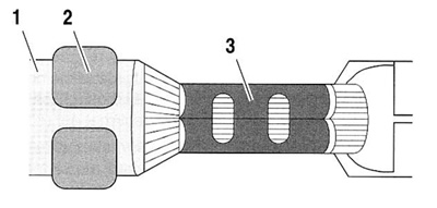
11. See Figure B-22. Inspect the quality of the core (3) and insulation/seal (2) crimps. Distortion should be minimal.

Figure B-22. Inspect core and insulation/seal crimps: 1. Insulation; 2. Insulation crimp; 3. Core crimp
Table B-2. Packard terminal crimp tools
| SPECIFICATION | PACKARD 115 | PACKARD 271 |
| Part No. | HD-38125-8 | HD-38125-7 |
| Type of Crimp | Non-sealed terminals, butt splices | Non-sealed terminals |
| Dye/nests | F-G | A-E |
