| PART NO. | SPECIALTY TOOL |
| HD-45654 | Clutch disc aligning spacer |
| HD-45318 | Clutch hub holder |
1. See Figure 3-90. Place flat steel damper spring seat on the clutch outer hub. Position the damper spring on the damper spring seat with concave side up.
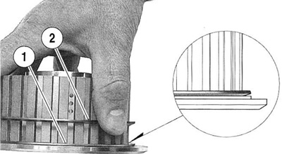
Figure 3-90. Damper spring position: 1. Damper spring seat; 2. Damper spring
Note. New plates should be soaked for 10 minutes in Harley-Davidson Motorcycle Oil 20W50 and assembled wet.
2. See Figure 3-91. See Figure 3-92. Install friction plate first and then a steel plate. Install the remaining plates (9 friction plates and 8 steel plates) in the same manner, alternating between friction plates and steel plates, ending with a friction plate.
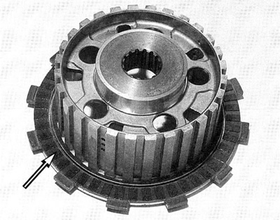
Figure 3-91. Friction plate
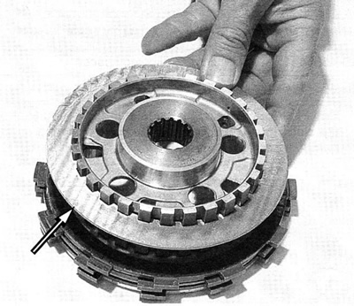
Figure 3-92. Steel plate
3. See Figure 3-93. Align ears on friction plates as shown.
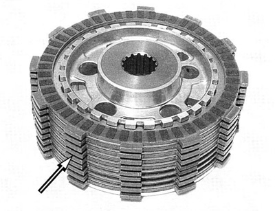
Figure 3-93. Align friction plates
4. See Figure 3-94. Note the alignment marks on the pressure plate and the clutch outer hub. The outer hub and pressure plate are balanced assemblies and must be aligned correctly.

Figure 3-94. Alignment marks
5. See Figure 3-95. Assemble the clutch hub (with plates in place) and pressure plate with the marks aligned as shown. Full engagement of hub and pressure plate will only occur if alignment is correct.
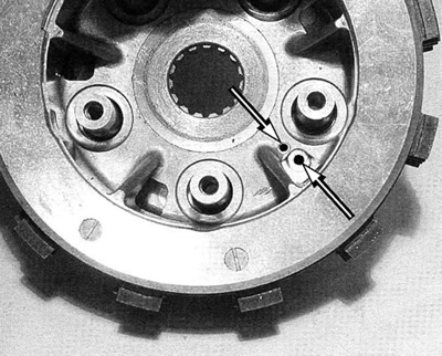
Figure 3-95. Align clutch outer hub and pressure plate
6. See Figure 3-96. Install the five pressure plate springs over the threaded bosses on the pressure plate. Position the lifter plate over the springs and install fasteners loose enough to allow the clutch plates to be moved for final alignment.
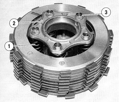
Figure 3-96. Align clutch hub and pressure plate: 1. Pressure plate springs; 2. Lifter plate; 3. Fasteners
7. See Figure 3-97. Insert distance collar in clutch basket as shown.

Figure 3-97. Distance collar
8. See Figure 3-98. Insert CLUTCH DISC ALIGNING SPACER (HD-45654) from the primary gear side.

Figure 3-98. Clutch disc aligning spacer (HD-45654)
9. See Figure 3-99. Align friction plate ears so clutch pack assembly drops into clutch basket under its own weight.

Figure 3-99. Insert clutch pack in clutch basket
10. See Figure 3-100. Top friction plate must be indexed to fit in the top slot of the clutch basket.
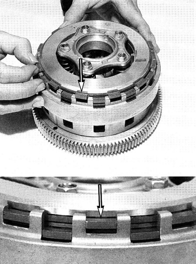
Figure 3-100. Align friction plates
11. See Figure 3-101. Using a crisscross pattern, tighten five spring screws to 9.7 Nm (85 in-lbs).

Figure 3-101. Spring screws
12. See Figure 3-102. Remove CLUTCH DISC ALIGNING SPACER (HD-45654).

Figure 3-102. Remove tool HD-45654
