
Bearing removal - 2nd gear end
| PART NO. | SPECIALTY TOOL |
| HD-45331 | Final drive sprocket flange locking tool |
1. See Figure 7-1. Remove lock ring from output flange nut.

Figure 7-1. Output shaft lock ring
2. See Figure 7-2. Place output shaft in FINAL DRIVE SPROCKET FLANGE LOCKING TOOL (HD-45331) to remove the output shaft nut, use a 30 mm socket cut down to 39.6 mm (1.56 in.) to clear the flange.

Figure 7-2. Modify socket for output nut removal
Note. Output flange nut is one time use only, but do not discard at this time. Retain removed nut to pull flange on shaft during assembly.
3. See Figure 7-3. Remove output shaft drive flange and seal retainer.

Figure 7-3. Output drive flange
4. See Figure 7-4. Remove output shaft bearing.

Figure 7-4. Output shaft bearing
Important note. If no further disassembly of this end is needed go to step 5. If further disassembly of this end is needed go to step 13.
Bearing installation - 2nd gear end
5. See Figure 7-5. and Figure 7-6. Lubricate new bearing. Position bearing on shaft with bearing alignment pin offset toward gears, and press onto shaft. Use a pressing ring so installation force is on the inner race only.
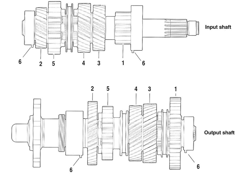
Figure 7-5. Transmission input shaft and output shaft assemblies: 1. 1st gear; 2. 2nd gear; 3. 3rd gear; 4. 4th gear; 5. 5th gear; 6. Bearing alignment pins (Install with offset toward gears)
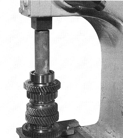
Figure 7-6. Output shaft bearing
6. See Figure 7-7. Replace flange seal and о-ring. Lubricate the flange seal with Harley-Davidson Motorcycle Oil 20W50.

Figure 7-7. Seal retainer
7. See Figure 7-8. Slide seal retainer on the output flange.

Figure 7-8. Seal retainer and output flange
Caution! Do not attempt to drive flange on with a hammer. Damage to the output shaft can result.

Figure 7-9. Install output shaft nut
9. Use the old output shaft nut to pull the output flange on the shaft.
10. See Figure 7-10. Remove and discard the old output shaft nut.

Figure 7-10. Tighten output shaft nut
11. Install a new о-ring behind the flange nut and install the new output shaft nut. Tighten nut to 160 Nm (118 ft-lbs).
12. See Figure 7-11. Position locking ring over the output shaft nut. Use FINAL DRIVE SPROCKET LOCKING DEVICE INSTALLER (HD-45332) to crimp in position.
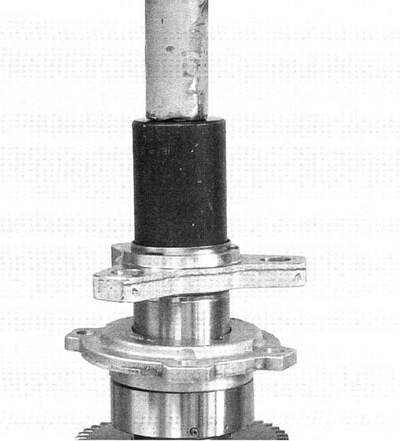
Figure 7-11. Output shaft nut lock ring - shaft out of engine
13. See Figure 7-12. If servicing flange or seals of assembled engine, locking ring may be installed as shown.

Figure 7-12. Output shaft nut lock ring - engine assembled
Caution! Never use a hammer to hit on the FINAL DRIVE SPROCKET LOCKING DEVICE INSTALLER (HD-45332). Damage to output shaft bearing could result.
14. See Figure 7-13. Remove ground washer.
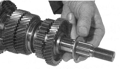
Figure 7-13. Remove ground washer
15. See Figure 7-14. Remove 2nd gear.

Figure 7-14. 2nd gear
16. See Figure 7-15. Remove split cage bearing and hardened washer.
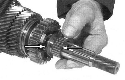
Figure 7-15. Bearing and washer
17. See Figure 7-16. Remove 5th gear.
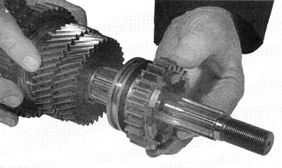
Figure 7-16. 5th gear
Note. 4th gear is part of output shaft and is not removable. Damage to 4th gear requires replacement of the output shaft.