
2. Before disassembling the master cylinder, read through the entire procedure and make sure that you have the correct rebuild kit. Also, you will need some new DOT 4 brake fluid, some clean rags and internal circlip pliers.
Note: To prevent damage to the paint from spilled brake fluid, always cover the surrounding components when working on the master cylinder.
Caution: Disassembly, overhaul and reassembly of the brake master cylinder must be done in a spotlessly clean work area to avoid contamination and possible failure of the brake hydraulic system components.
Removal
3. Remove the right-hand side panel (see Chapter 8). On XRV750-L to N (1990 to 1992) models, unscrew the bolts securing the righthand passenger footrest bracket and remove it. noting how it fits.
4. Unscrew the bolt securing the master cylinder reservoir (see illustrations). Undo the two reservoir cover screws or unscrew ths reservoir cap (according to model), anc remove the diaphragm plate and diaphragm, then pour the fluid into a container Separate the fluid reservoir hose from the union on the master cylinder by releasing the hose clamp (see illustration).
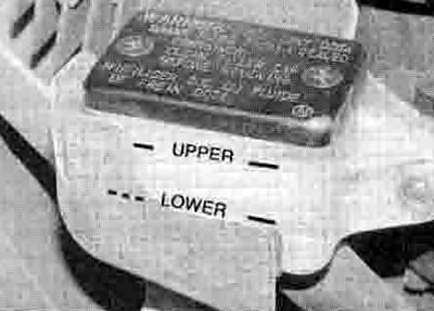
8.4a. Master cylinder reservoir - XL600V
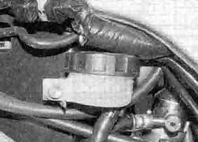
8.4b. Master cylinder reservoir - XRV750

8.4c. Reservoir hose clamp (A), master cylinder mounting bolts (B)
5. Unscrew the brake hose banjo bolt and separate the hose from the master cylinder noting its alignment (see illustration). Discard the sealing washers as they must be replaced with new ones. Wrap the end of the hose in a clean rag and suspend it in an upright position, or bend it down carefully and place the open end in a clean container. Ths objective is to prevent excessive loss of brake fluid, fluid spills and system contamination.
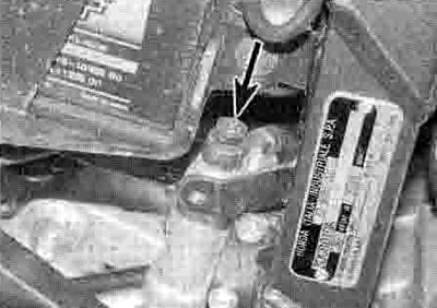
8.5. Brake hose banjo bolt (arrowed)
6. Remove the split pin from the clevis pm securing the brake pedal to the master cylinder pushrod, then remove the clevis pin and separate the pedal from the pushrod (see illustrations).

8.6a. Remove the split pin...

8.6b ...then withdraw the clevis pin
7. Unscrew the two bolts securing the master cylinder to the bracket and remove the master cylinder (see illustration 8.4c).
Overhaul
8. If required, and where it is not secured by a roll pin, mark the position of the clevis locknut on the pushrod, then slacken the locknut and thread the clevis and its base nut off the pushrod (see illustration). If a roll pin is fitted, it will have to he drifted out.
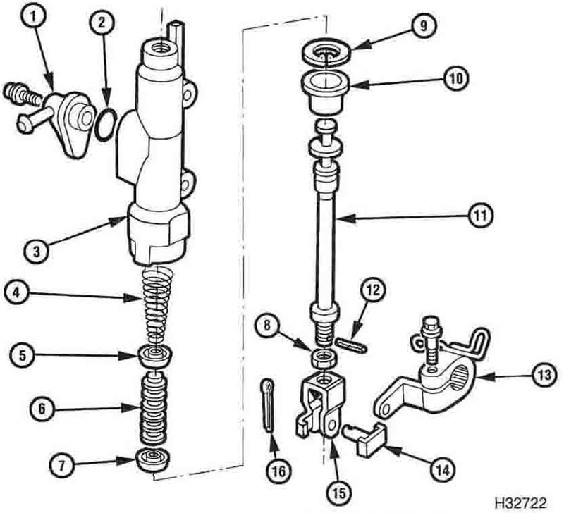
8.8. Rear master cylinder components: 1. Reservoir hose union; 2. O-ring; 3. Master cylinder; 4. Spring; 5. Cup; 6. Piston; 7. Seal; 8. Nut; 9. Circlip; 10. Rubber boot; 11. Pushrod; 12. Roll pin; 13. Brake pedal arm; 14. Clevis pin; 15. Clevis; 16. Split pin
9. Dislodge the rubber dust boot from the base of the master cylinder and from around the pushrod. noting how it locates, and slide it up the pushrod.
10. Push the pushrod in and, using circlip pliers, remove the circlip from its groove in the master cylinder and slide out the piston assembly and the spring, noting how they fit. If they are difficult to remove, apply low pressure compressed air to the fluid outlet. Lay the parts out in the proper order to prevent confusion during reassembly.
11. If required, remove the screw securing the fluid reservoir hose union and detach it from the master cylinder. Discard the О-ring as a new one must be used. Inspect the reservoir hose for cracks or splits and replace with a new one if necessary.
12. Clean all of the parts with clean brake fluid or denatured alcohol.
Caution: Do not, under any circumstances, use a petroleum-based solvent to clean brake parts. If compressed air is available, use it to dry the parts thoroughly (make sure it's filtered and unlubricated).
13. Check the master cylinder bore for corrosion, scratches, nicks and score marks. If the necessary measuring equipment is available, compare the dimensions of the piston and bore to those given in the Specifications Section of this Chapter. If damage or wear is evident, the master cylinder must be replaced with a new one. If the master cylinder is in poor condition, then the caliper should be checked as well.
14. The dust boot, circlip, piston, seal, cup and spring are included in the rebuild kit. Use all of the new parts, regardless of the apparent condition of the old ones. If the seal is not already on the piston, fit it according to the layout of the old one. Slide the new boot onto the pushrod, making sure it is the correct way round.
15. Fit the cup over the end of the spring so that its inner raised section tits into the outer coil on the spring. Lubricate the cup, seal and piston with clean brake fluid.
16. Install the spring in the master cylinder with the cup facing out, then fit the piston into the master cylinder, making sure it is the correct way round. Make sure the lips on the cup and seal do not turn inside out when they enter the bore.
17. Apply some silicone grease to the end of the pushrod and fit it into the master cylinder. Depress the pushrod, then install the new circlip, making sure it is properly seated in the groove.
18. Install the rubber dust boot, making sure it is seated properly in the groove in the master cylinder and around the pushrod.
19. If removed, fit a new О-ring to the fluid reservoir hose union, then fit the union onto the master cylinder and secure it with its screw.
20. If removed, thread the clevis locknut and the clevis onto the master cylinder pushrod end. Set the clevis position as noted on removal. Honda specify the distance between the eye in the clevis and the lower mounting bolt hole should be 100 mm. Tighten the clevis locknut securely against the clevis.
21. Where the clevis is retained by a roll pin. secure it in position with a new pin.
Installation
22. Fit the master cylinder onto the footrest bracket and tighten its mounting bolts to the torque setting specified at the beginning of the Chapter (see illustration 8.4c).
23. Align the brake pedal with the master cylinder pushrod clevis, then slide in the clevis pin and secure it using a new split pin (see illustrations 8.6b and a).
24. Connect the brake hose to the master cylinder, using new sealing washers on each side of the union. Align the hose as noted on removal and tighten the banjo bolt to the specified torque setting (see illustration 8.5).
25. Fit the fluid reservoir on its mount and secure it with its bolt (see illustration 8.4a or b). Ensure that the hose is correctly routed then connect it to the union on the master cylinder and secure it with the clamp (see illustration 8.4c). Check that the hose is secure and clamped at the reservoir end as well. If the clamps have weakened, use new ones.
26. Fill the fluid reservoir with new DOT 4 brake fluid (see Daily (pre-ride) checks) and bleed the system following the procedure in Section 10.
27. Check the operation of the brake and brake light carefully before riding the motorcycle.
28. On XRV750-L to N (1990 to 1992) models, install the right-hand passenger footrest bracket and tighten its bolts securely. Install the right-hand side panel (see Chapter 8).