
Warning: If a caliper indicates the need for an overhaul (usually due to leaking fluid or sticky operation), all old brake fluid should be flushed from the system Also, the dust created by the brake system may contain asbestos, which is harmful to your health. Never blow it out with compressed air and don't inhale any of it. An approved filtering mask should be worn when working on the brakes. Do not, under any circumstances, use petroleum-based solvents to clean brake parts. Use clean brake fluid, brake cleaner or denatured alcohol only.
Removal
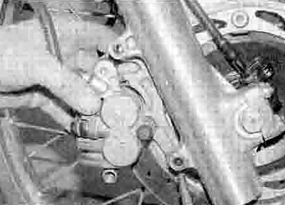
1. If the caliper is just being displaced and not completely removed or overhauled, do no! disconnect the brake hose. If the caliper is being completely removed or overhauled, remove the brake hose banjo bolt and detach the hose, noting the alignment with the caliper (see illustration). Plug the hose end or wrap a plastic bag tightly around to minimise fluid loss and prevent dirt entering the system. Discard the sealing washers as new ones must be used on installation. Note: If you are planning to overhaul the caliper and don't have a source of compressed air to blow out the piston, just loosen the banjo bolt at this stage and retighten it lightly. The bike's hydraulic system can then be used to force the piston out of the body once the pads have been removed. Disconnect the hose once the piston have been sufficiently displaced.
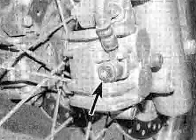
4.1. Brake hose banjo bolt (arrowed)
2. On XRV models, remove the fork guards (see Chapter 8). On all models, unscrew the bolt securing the brake hose in the clamp on the front fork and release it, noting how it fits (see illustration 2.3).
3. If the caliper is being overhauled, remove the brake pads (see Section 2). On XL600V-H to P (1987 to 1993) models and XRV750-L to N (1990 to 1992) models this involves removing the calipers, so ignore Step 4.
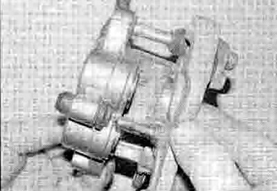
4. Unscrew the caliper bracket mounting bolts and slide the caliper assembly off the disc (see illustration).

4.4. Unscrew the bolts (arrowed) and slide the caliper off the disc
Overhaul
Refer to illustrations 2.4a, 2.4b and 2.18d for exploded views of the caliper.
5. Separate the caliper from the bracket by sliding them apart (see illustration). If required, remove the pad spring from the caliper and the guide from the bracket, noting how they fit (see illustrations).
4.5a. Separate the caliper and bracket...
4.5b ...and remove the pad spring (arrowed)...
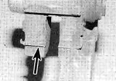
4.5c ...and the pad guide (arrowed) - late model XL600V shown
6. Clean the exterior of the caliper with denatured alcohol or brake system cleaner.
7. Remove the pistons from the caliper body, either by pumping them out by operating the brake pedal, or by using compressed air. If the compressed air method is used, place a wad of rag over the pistons to act as a cushion, then use compressed air directed into the fluid inlet to force the pistons out of Ilie body. Use only low pressure to ease the pistons out, and make sure they are displaced at the same time. If the air pressure is too high and a pistons are forced out, the caliper and/or pistons may be damaged.
Warning: Never place your fingers if in front of the piston in an attempt to catch or protect it when applying compressed air, as serious injury could result. Place the caliper piston side down on a bench, with the rag between them, and let the air lift the caliper off the piston.
Caution: Do not try to remove the pistons by levering them out, or by using pliers or any other grips.
8. Using a wooden or plastic tool, remove the dust seals from the caliper bore. Discard them as new ones must be used on installation. If a metal tool is being used, take great care not to damage the caliper bores.
9. Remove and discard the piston seals In the same way.
10. Clean the pistons and bores with denatured alcohol, clean brake fluid or brake system cleaner. If compressed air is available, use it to dry the parts thoroughly (make sure it's filtered and unlubricated).
Caution: Do not, under any circumstances, use a petroleum-based solvent to clean brake parts.
11. Inspect the caliper bores and pistons for signs of corrosion, nicks and burrs and loss of plating. If surface defects are present, the caliper and/or pistons must be replaced with new ones. If the necessary measuring equipment Is available, compare the dimensions of the pistons and bores to those given in the Specifications Section of this Chapter, replacing any component that is worn beyond its service limit. If the caliper is in bad shape the master cylinder should also be checked.
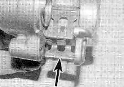
12. Remove the slider pin rubber boots from the caliper and the bracket (see illustration). Clean off all traces of corrosion and hardened grease from the boots and pins. Renew the rubber boots if they are damaged, deformed or deteriorated. Apply a smear of silicone based grease to the boots and slider pins. Fit the boots into their bores.
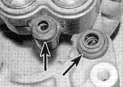
4.12. Remove the rubber boots (arrowed)
13. Lubricate the new piston seals with clean brake fluid and fit them in their grooves in the caliper bores. Note that on XL650V models different sizes of bore and piston are used (see Specifications), and care must therefore be taken to ensure that the correct size seals are fitted to the correct bores. The same applies when fitting the new dust seals and pistons.
14. Lubricate the new dust seals with clean brake fluid and fit them in their grooves in the caliper bore.
15. Lubricate the pistons with clean brake fluid and fit them closed-end first into the caliper bores. Using your thumbs, push the pistons all the way in, making sure they enter the bore squarely.
16. Make sure that the pad spring and pad guide are correctly fitted (see illustrations 4.5b and c) Slide the caliper and bracket together (see illustration 4.5a).
Installation
17. If Ihe caliper has not been overhauled, separate the caliper from the bracket by sliding them apart (see illustration 4.5a). Remove the slider pin rubber boots from the caliper and the bracket (see illustration 4.12). Clean off all traces of corrosion and hardened grease from the boots and pins. Renew the rubber boots if they are damaged, deformed or deteriorated. Apply a smear of silicone based grease to the boots and slider pins. Fit the boots into their bores. Make sure that the pad spring and pad guide are correctly fitted (see illustrations 4.5b and c)
18. If the caliper has been overhauled, install the brake pads (see Section 2).
19. Slide the caliper onto the disc making sure the pads locate on each side (see illustration). Apply a suitable non-permanent thread-locking compound to the mounting bolts and tighten them securely.
4.19. Slide the caliper onto the disc and install the bolts
20. If detached, connect the brake hose to the caliper, using new sealing washers on each side of the fitting. Align the hose as noted on removal (see illustration 4.1). Tighten the banjo bolt to Ihe torque setting specified at the beginning of the Chapter.
21. Fit the brake hose into its clamp on the front fork and secure it with the bolt.
22. Fill the master cylinder reservoir with DOT 4 brake fluid (see Daily (pre-ride) checks) and bleed the hydraulic system as described in Section 10.
23. Check for leaks and thoroughly test the operation of the brake before riding the motorcycle.