| DETECTED CONDITION | POSSIBLE CAUSE | ||
| C40 P0505 | H | ISC valve motor current is higher than the specified value. | ISC valve circuit shorted to BATT or ground circuit open |
| L | ISC valve motor circuit is open. | ISC valve circuit open or shorted to ground or BATT circuit open | |
| P0506 | Idle speed is lower than the desired idle speed. | W/Y or Lg wire open or short ISC valve is fixed Air curcuit clogged | |
| P0507 | Idle speed is higher than the desired idle speed. | W/Y or Dgr wire open or short Disconnected ISC valve hose | |
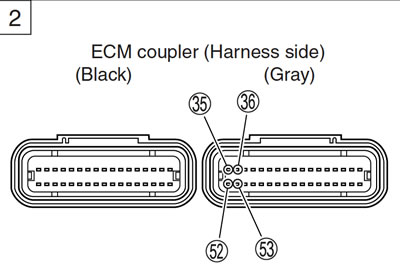
Caution: Be careful not to disconnect at least 3 seconds after ignition switch is turned to OFF. If the ECM coupler is disconnected within 3 seconds after ignition switch is turned to OFF, there is a possibility of an usual valve being written in ECM and causing an error of ISC valve operation.
Inspection
Step 1
- 1) Remove the fuel tank. (6-3)
- 2) Turn the ignition switch OFF.
- 3) Check the ISC valve coupler for loose or poor contacts.
- 4) If OK, then check the ISC valve lead wire continuity.
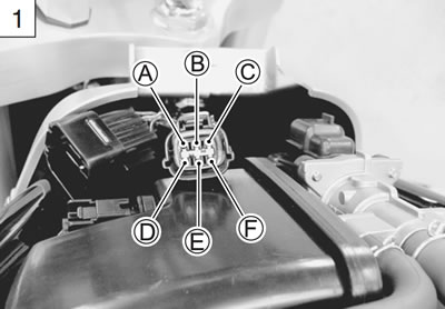
- 5) Disconnect the ISC valve coupler and ECM coupler. (5-37)
- 6) Check the continuity between terminals А and 53, terminals В and 16, terminals С and 36, terminals D and 52, terminals E and 16, and terminals F and 45.
Caution: When using the multi-circuit tester, do not strongly touch the terminal of the ECM coupler with a needle pointed tester probe to prevent the terminal damage or terminal bend.
- ISC valve wire continuity: Continuity (•)))
- 09900-25008: Multi-circuit tester set
- 09900-25009: Needle pointed probe set
- Tester knob indication: Continuity test (•)))
Is the continuity OK?
| YES | Go to Step 2. |
| NO | Lbl, W/Y, Dgr, R/Bl or Lg wire open. |
- 7) After repairing the trouble, clear the DTC using SDS tool. (5-26)
Step 2
- 1) Turn the ignition switch OFF.
- 2) Disconnect the ISC valve coupler.
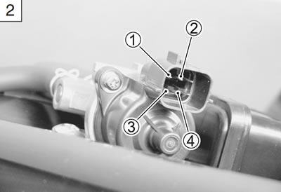
- 3) Check the continuity between terminals 1 and 3, terminals 2 and 4.
- ISC valve continuity: Approx. ∞ Ω (Infinity)
- (Terminal 1 - Terminal 3)
- (Terminal 2 - Terminal 4)
- 4) If OK, then measure the resistance between terminals 1 and 2, terminals 3 and 4.
- ISC valve resistance: Approx. 30±1.2 Ω at 20°C (68°F)
- (Terminal 1 - Terminal 3)
- (Terminal 2 - Terminal 4)
Is the resistance OK?
| YES | If wire is OK, intermittent trouble or faulty ECM. |
| NO | Replace the ISC valve with a new one. |
- 5) After repairing the trouble, clear the DTC using SDS tool. (5-26)
Active control inspection (ISC RPM Control)
Check 1
- 1) Set up the SDS tool. (Refer to the SDS operation manual for further details.)
- 2) Check that the engine is running.
- 3) Click the "Active control".
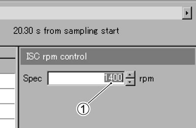
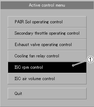
- 4) Click the "ISC rpm control" 1.

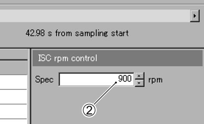
- 5) Check that the "Spec" 2 is 900 rpm.
- 6) Check that the "Desired idle speed" 3 is 900 rpm.

Check 2
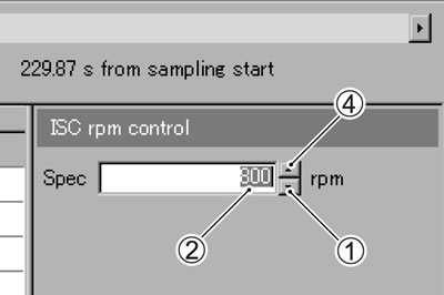
- 1) Click the button 1 and decrease the "Spec" 2 to 800 rpm slowly.
- 2) Check that the "Desired idle speed" 3 is nearly equal to the "Spec" 2. At the same time, check that the number of steps in the ISC valve position decreases.
- 3) Click the button 4 and increase the "Spec" 2 slowly.
- 4) Check that the "Desired idle speed" 3 is nearly equal to the "Spec" 2. Also, check that the number of steps 5 in the ISC valve position increases.

Check 3
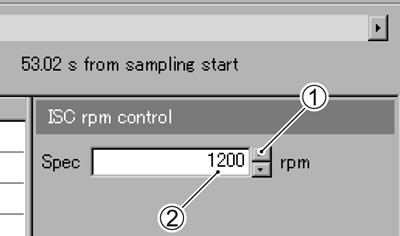
- 1) Click the button 1 and increase the "Spec" 2 to 1 200 rpm slowly.
- 2) Check that the "Desired idle speed" 3 is nearly equal to the "Spec" 2. Also, check that the number of steps 4 in the ISC valve position increases.
Caution: Be careful not to increase the "Spec" to 1 500 rpm, or the "Engine speed" may reach the upper limit.
