MotoInstruction.ru
Mobile
version
Articles
& news
Site
map
Feed
back
Add to
bookmark
English Русский
Aprilia
BMW
Ducati
Harley
Honda
Kawasaki
Suzuki
Triumph
Yamaha
Aprilia:
RS-series▾
RS125 [3] (1998-2005)
Shiver▾
SL750 (2007-2016)

Rave valve circuit (Aprilia RS125/3)

  • Main
  • Aprilia
  • RS-series
  • RS 125 [3]
  • Electric equipment
  • Equipment and devices
  • Rave valve circuit
0


The RAVE control unit operates the solenoid to open the valve at the exhaust end at 8100 rpm.

Troubleshooting


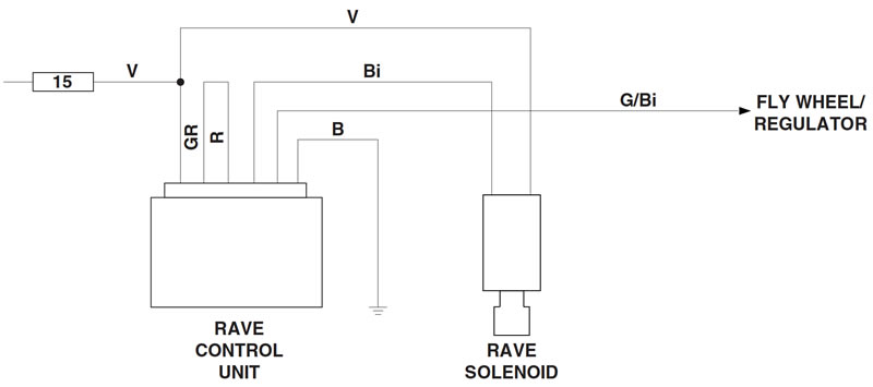
Check the condition of the 15 A fuse.

Attach a 12V battery direct to the solenoid to check for proper operation.

Check the flywheel; see 8.6.1.

Fit a substitute regulator known to operate correctly.

Fit a substitute RAVE control unit known to operate correctly.

Warning! Cut the jumper across the grey and red wires of the RAVE control unit and the solenoid will operate the valve at 7,800 rpm.


Control unit


Remove the fuel tank; see 4.1.1.

Remove the battery and battery box mount together; see 7.2.1.

Disconnect the connector.

Start the engine and switch on the low beam.

Speed up engine up to 2500 rpm.

Measure voltage across the green (V) and blue (B) wires using a multimeter: Correct reading = 12.25±1 VDC.


Measure voltage across the yellow (G) and blue (B) wires using a multimeter: Correct reading = 8.5±1 VAC.


Note. Any readings other than the specified values indicate a fault in the system, not in the control unit.


Solenoid


Check that the piston moves freely.

Start the engine and let it idle.

Measure resistance across the wires using a multimeter: Correct reading = 2.2 Ohms±10%.

Measure voltage across the solenoid wires using a multimeter: Correct reading = 11.5±1 V at idling speed during a single one-second pulse. After this initial pulse, reading should drop to 5.5±1 VDC.
See this article in russian language
◀ Previous
Aprilia RS125 3: Equipment and devices
Next ▶

Light circuit of motorcycle
Brake lights circuit
Visual and acoustic signalling system
Sensors and rev counter circuit
Wiring colour codes and electrical connectors
Layout of electrical components
Stand logic circuit
Bulb replacement
Replacing the fuses
Beam height setting
Wiring diagram of motorcycle
Similar articles about motorcycles of other brands
Kawasaki ZX6R/ZX600J (2000-2002): Fuel cut valve circuit Suzuki V-Strom DL-650 (2004-2011): «C49» PAIR control solenoid valve circuit malfunction Yamaha FZ1 Fazer (2006-2015): Ignition circuit breaker system Triumph Rocket III (2004-2018): Valve clearances Honda CB 400 SF (1992-1999): Cylinder head — checking and adjusting valve clearances Ducati ST2 (1997-2003): Checking valve clearances Harley-Davidson V-Rod (2002-2006): Valve lash measurment BMW R 1150 GS (1999-2004): Bleeding front brake circuit/changing brake fluid
Link to this article in different formats
TEXTHTMLBB Code
Comments and feedback from visitors
No comments yet, you will be the first!


Add up two numbers: 32 + 31


RS125 3 (1998-2005) 
  • Information for owner
  • Introduction to manual
  • Maintenance
  • Troubleshooting
  • Engine and systems
  • Engine repair
  • Fuel system
  • Cooling and lube system
  • Running gear and frame
  • Frame and hinged elements
  • Front suspension and handlebar
  • Rear suspension
  • Brake system
  • Wheels and tires
  • Electric equipment
  • Equipment and devices
  • Starting and charging system
Aprilia BMW Ducati Harley Honda Kawasaki Suzuki Triumph Yamaha
MotoInstruction.ru © 2021–2025 | Sitemap | Articles | Contacts | Site search | Add to bookmarks | Mobile version