| DETECTED CONDITION | POSSIBLE CAUSE | ||
| C29 | Signal voltage is not within the following range. Difference between actual throttle open- | STP sensor maladjusted STP sensor circuit open or short STP sensor malfunction | |
| P1654 | ing and opening calculated by ECM is larger than specified value. 0.15 V ≤ Sensor voltage < 4.85 V | ECM malfunction | |
| P1654 | H | Sensor voltage is higher than specified value. | STP sensor circuit shorted to VCC or ground circuit open |
| L | Sensor voltage is lower than specified value. | STP sensor circuit open or shorted to ground or VCC circuit open | |
Inspection
Step 1 (When indicating C29:)
- 1) Turn the ignition switch OFF.
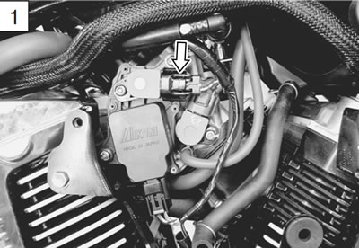
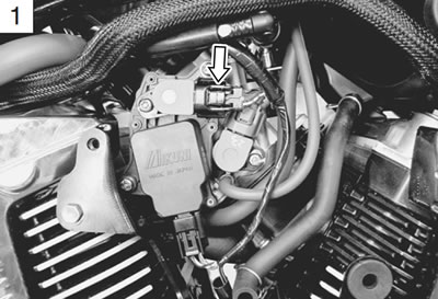
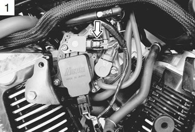
- 2) Remove the right air cleaner box. (6-13)
- 3) Check the STP sensor coupler for loose or poor contacts.
If OK, then measure the STP sensor input voltage.
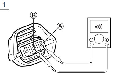
- 4) Disconnect the STP sensor coupler. (Black)
- 5) Turn the ignition switch ON.
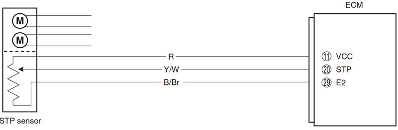
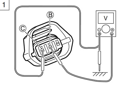
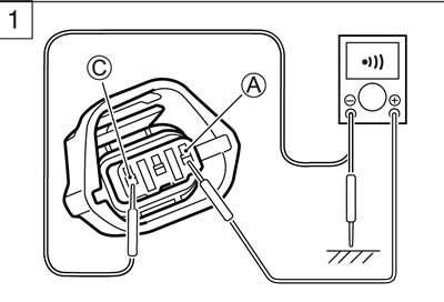
- 6) Measure the voltage at the Red wire B and ground.
- 7) If OK, then measure the voltage at the Red wire B and B/Br wire C.
- STP sensor input voltage: 4.5 - 5.5 V
- (+ Red - − Ground)
- (+ Red - − B/Br)
- 09900-25008: Multi-circuit tester set
- Tester knob indication: Voltage
Is the voltage OK?
| YES | Go to Step 2. |
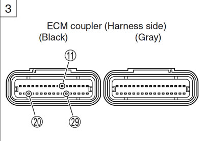
| NO | Loose or poor contacts on the ECM coupler (terminal 11 or 29) Open or short circuit in the Red wire or B/Br wire |
Step 1 (When indicating P1654-H:)
- 1) Turn the ignition switch OFF.
- 2) Remove the right air cleaner box. (6-13)
- 3) Check the STP sensor coupler for loose or poor contacts. If OK, then check the STP sensor lead wire continuity.
- STP sensor lead wire coupler: Black
- 4) Disconnect the STP sensor coupler.
- 5) Check the continuity between Y/W wire A and Red wire B.
If the sound is not heard from the tester, the circuit condition is OK.
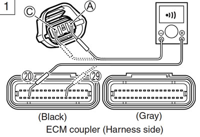
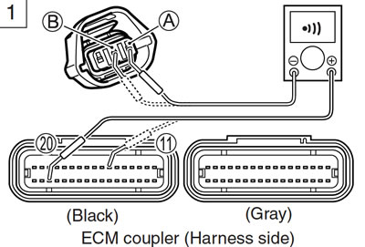
- 6) Disconnect the ECM coupler. (5-37)
- 7) Check the continuity between Y/W wire A and terminal 20.
- 8) Also, check the continuity between B/Br wire C and terminal 29.
Caution: When using the multi-circuit tester, do not strongly touch the terminal of the ECM coupler with a needle pointed tester probe to prevent the terminal damage or terminal bend.
- STPS lead wire continuity: Continuity (•)))
- 09900-25008: Multi-circuit tester set
- 09900-25009: Needle pointed probe set
- Tester knob indication: Continuity test (•)))
Is the continuity OK?
| YES | Go to Step 2. |
| NO | Y/W wire shorted to VCC, or B/Br wire open |
- 9) After repairing the trouble, clear the DTC using SDS tool. (5-26)
Step 1 (When indicating P1654-L:)
- 1) Turn the ignition switch OFF.
- 2) Remove the right air cleaner box. (6-13)
- 3) Check the STP sensor coupler for loose or poor contacts. If OK, then check the STP sensor lead wire continuity.
- STP sensor lead wire coupler: Black
- 4) Disconnect the STP sensor coupler.
- 5) Check the continuity between Y/W wire A and ground.
- 6) Also, check the continuity between Y/W wire A and B/Br wire C. If the sound is not heard from the tester, the circuit condition is OK.
- 7) Disconnect the ECM coupler. (5-37)
- 8) Check the continuity between Y/W wire A and terminal 20.
- 9) Also, check the continuity between Red wire B and terminal 11.
Caution: When using the multi-circuit tester, do not strongly touch the terminal of the ECM coupler with a needle pointed tester probe to prevent the terminal damage or terminal bend.
- STPS lead wire continuity: Continuity (•)))
- 09900-25008: Multi-circuit tester set
- 09900-25009: Needle pointed probe set
- Tester knob indication: Continuity test (•)))
Is the continuity OK?
| YES | Go to Step 1 (5-61) and go to Step 2. |
| NO | Red or Y/W wire open, or Y/W wire shorted to ground |
- 10) After repairing the trouble, clear the DTC using SDS tool. (5-26)
Step 2
- 1) Turn the ignition switch OFF.
- 2) Remove the air cleaner chamber. (6-13)
- 3) Disconnect the STP sensor coupler.
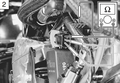
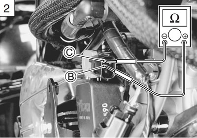
- 4) Check the continuity between each terminal and ground.
- STP sensor continuity: ∞ Ω (Infinity)
- (Terminal - Ground)
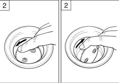
- 5) If OK, then measure the STP sensor resistance at the terminals (between Y/W wire A and B/Br wire C).
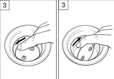
- 6) Close and open the secondary throttle valve by finger, and measure the valve closing and opening resistance.
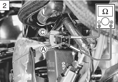
STP sensor resistance:
- Secondary throttle valve is closed: Approx. 0.6 kΩ
- Secondary throttle valve is opened: Approx. 4.2 kΩ
- (Y/W B - B/Br C)
- 7) If OK, then measure the STP sensor resistance at the terminals (between Red wire B and B/Br wire C).
STP sensor resistance:
- Approx. 5.0 kΩ
- (Red B - B/Br C)
- 09900-25008: Multi-circuit tester set
- Tester knob indication: Resistance (Ω)
Are the continuity and resistance OK?
| YES | Go to Step 3. |
| NO | Reset the STP sensor position correctly. Replace the STP sensor with a new one. |
- 8) After repairing the trouble, clear the DTC using SDS tool. (5-26)
Step 3
- 1) Turn the ignition switch OFF.
- 2) Disconnect the STP sensor coupler and install the test harness.
- 3) Disconnect the STVA lead wire coupler.
- 4) Turn the ignition switch ON.
- 5) Measure the STP sensor output voltage at the terminals (between + terminal A Y/W wire and − terminal C B/Br wire) by turning the secondary throttle valve (close and open) with a finger.
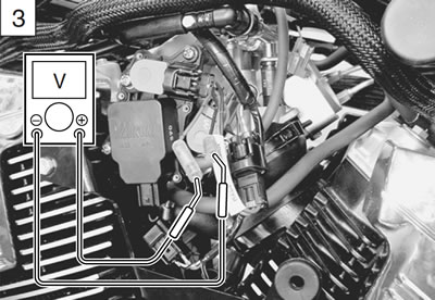
STP sensor output voltage:
- Secondary throttle valve is closed: Approx. 0.6 V
- Secondary throttle valve is opened: Approx. 4.2 V
- 09900-25008: Multi-circuit tester set
- 09900-28630: TPS test wire harness
- Tester knob indication: Voltage
Is the voltage OK?
| YES | Red, Y/W or B/Br wire open or shorted to ground, or poor 11, 20 or 29 connection If wire and connection are OK, intermittent trouble or faulty ECM. Recheck each terminal and wire harness for open circuit and poor connection. Replace the ECM with a known good one, and inspect it again. |
| NO | If check result is not satisfactory, replace STP sensor with a new one. |
After repairing the trouble, clear the DTC using SDS tool. (5-26)